I would like to present you a section of my bachelor thesis, which I wrote at the Ruhr University Bochum (December 2018). The concept ideas, the text and the images were created by me.
In recent decades, the demand for new and individual products has increased. The resulting increase in product complexity and diversity requires flexible manufacturing options. The product life cycle, on the other hand, is decreasing due to global competition and product individualization1. The company’s success is therefore tied to new product developments. Product release is also an important component of success. If a product is introduced late, it may have already been replaced by other products. The aim of the current development is to develop new manufacturing possibilities and tools that are more economical, faster and more flexible2.
Additive processes have become a trend due to the cost-effective and flexible manufacturing of products, but there is a lack of optimization potential with regard to quality and speed at higher volumes3. In contrast, machining processes offer higher speeds and quality requirements for manufacturing, but product manufacturing is associated with much higher costs, resulting in poorer cost recovery for custom products2 4.
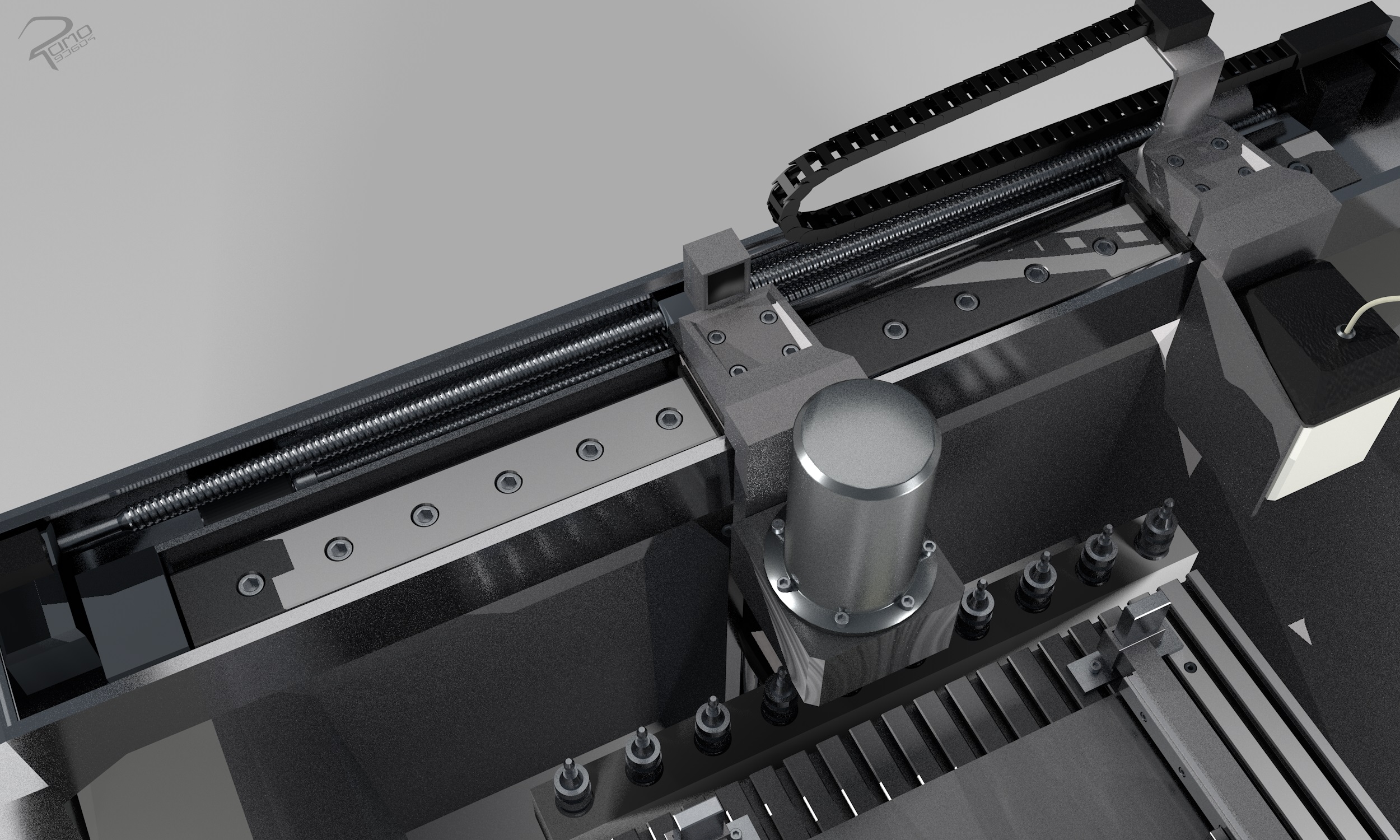
The aim of the work is to develop a new hybrid system concept to improve the persistent points regarding the manufacturing deficits. The two processes of fused layer modeling and milling are to be combined into a single system. It is also hoped that this combination will reduce the disadvantages of the individual systems. It must be checked whether the two processes are compatible with each other and, in addition, whether they achieve the defined goals when they are merged. The system should cover the existing areas of application and create new ones.
The following four goals were pursued in the conceptual design:
- Increase in surface finish (smoothing) and reduction of post-processing of printed geometries.
- Products made of mixed materials (multimaterial)
- Advanced function integration
- Use of two different methods
Note:
Fused Layer Modeling (FLM) is an additive manufacturing process that was developed at the end of the 1980s. In the FLM process, the geometry model is generated layer by layer from the bottom up. The layers are created by heating and extruding fusible material with a nozzle or print head. The fusible material extruded through the print head or nozzle solidifies shortly after it exits so that the layers can be printed on top of each other without changing shape5.
Computerized Numerical Control (CNC) In the subtractive process, the blank is brought into a defined shape by removing the material with the aid of tools. A distinction is made here between non-cutting and cutting production. In machining, material is removed using mechanical tools6.
The construction model is the result of the elaboration of various concepts and ideas. These ideas and concepts are presented in the following section.
Frame and guide system
In this section, several concepts of the rack and guide system are presented
The frame has the task of defining the shape and structure of the machine. The structure and shape includes the respective positions of the machine parts and the absorption of the mechanical and thermal loads. Guides are used for the moving machine parts, which enable rotary and linear movements7. The guides determine the direction of movement by limiting the degrees of freedom of movement. The guides and the frame absorb forces and torques when the tool engages the workpiece8.
Frame Concept 1
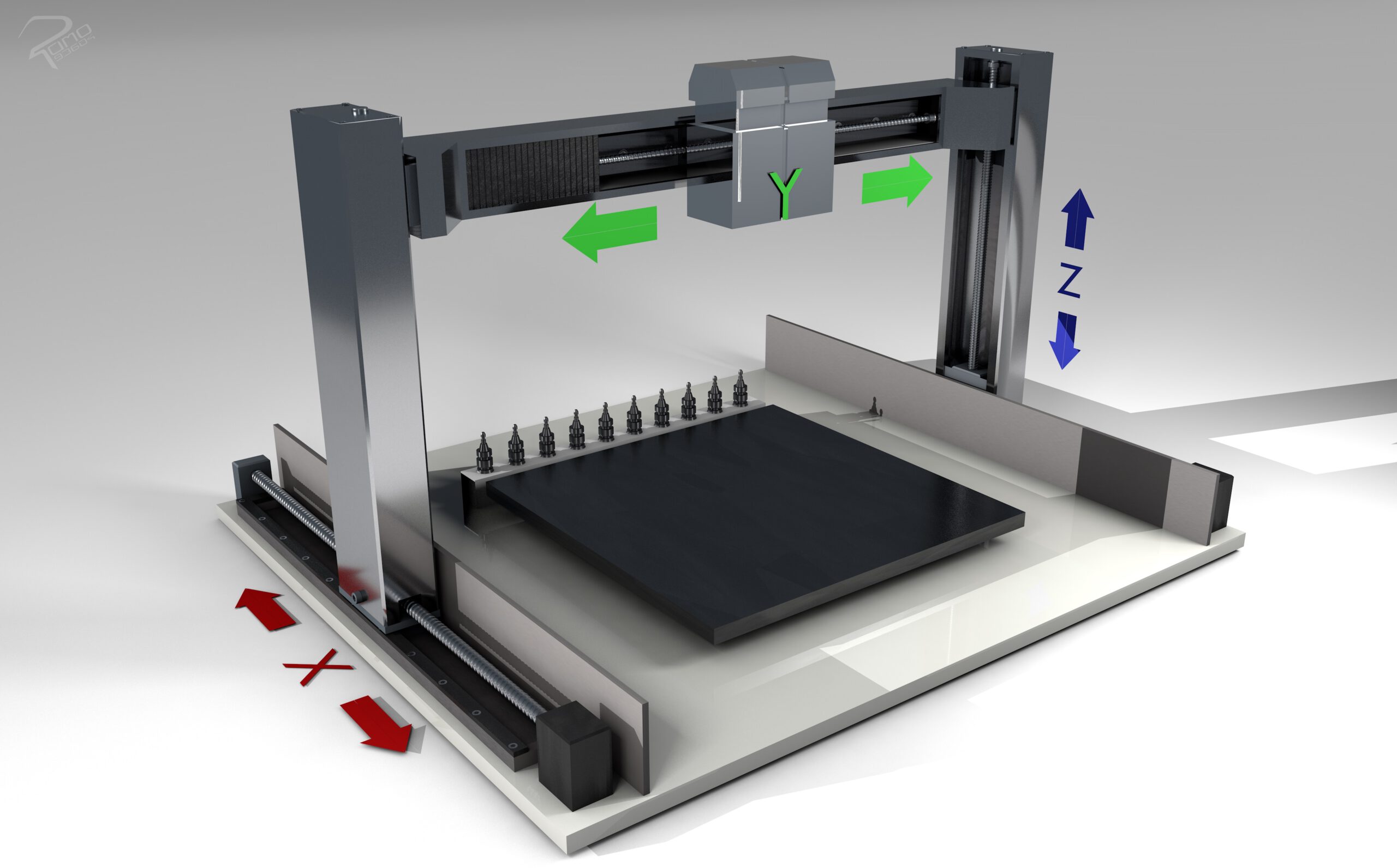
This concept is in the form of a gantry-type machine. The extruder and milling unit is guided over a crossbeam and two stands. The head can move over the beam and the cross beam over the stand. The stand can move over the base.
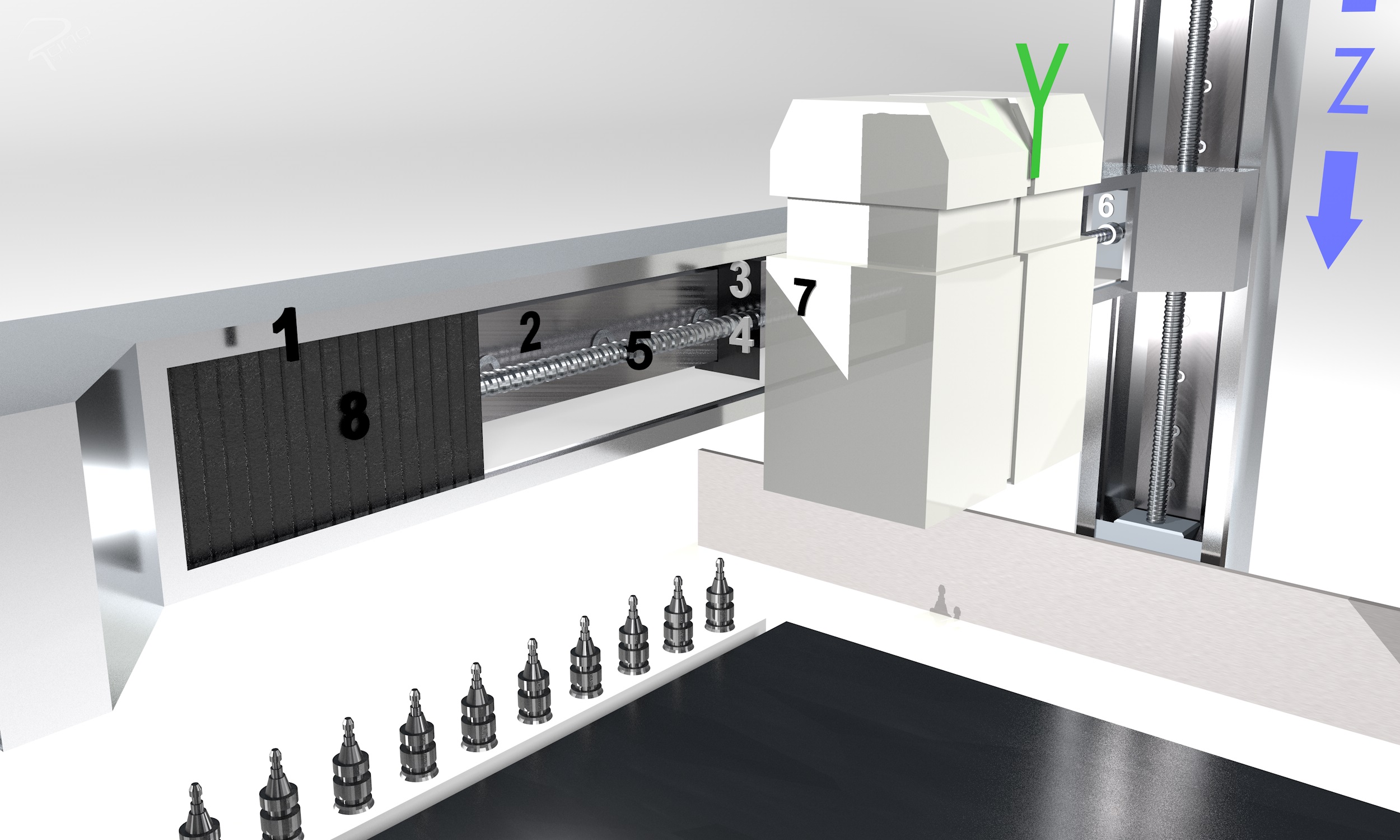
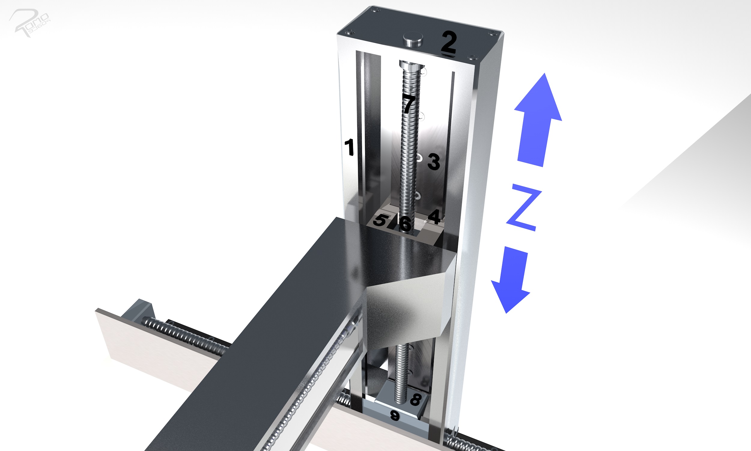
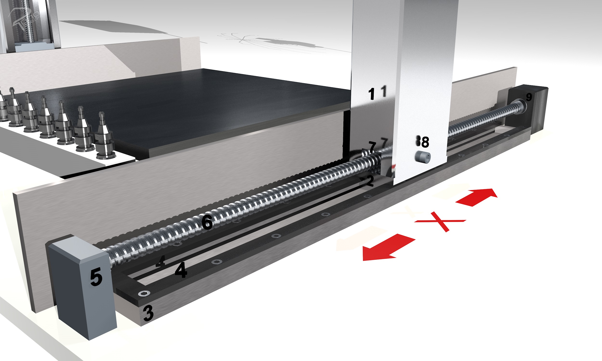
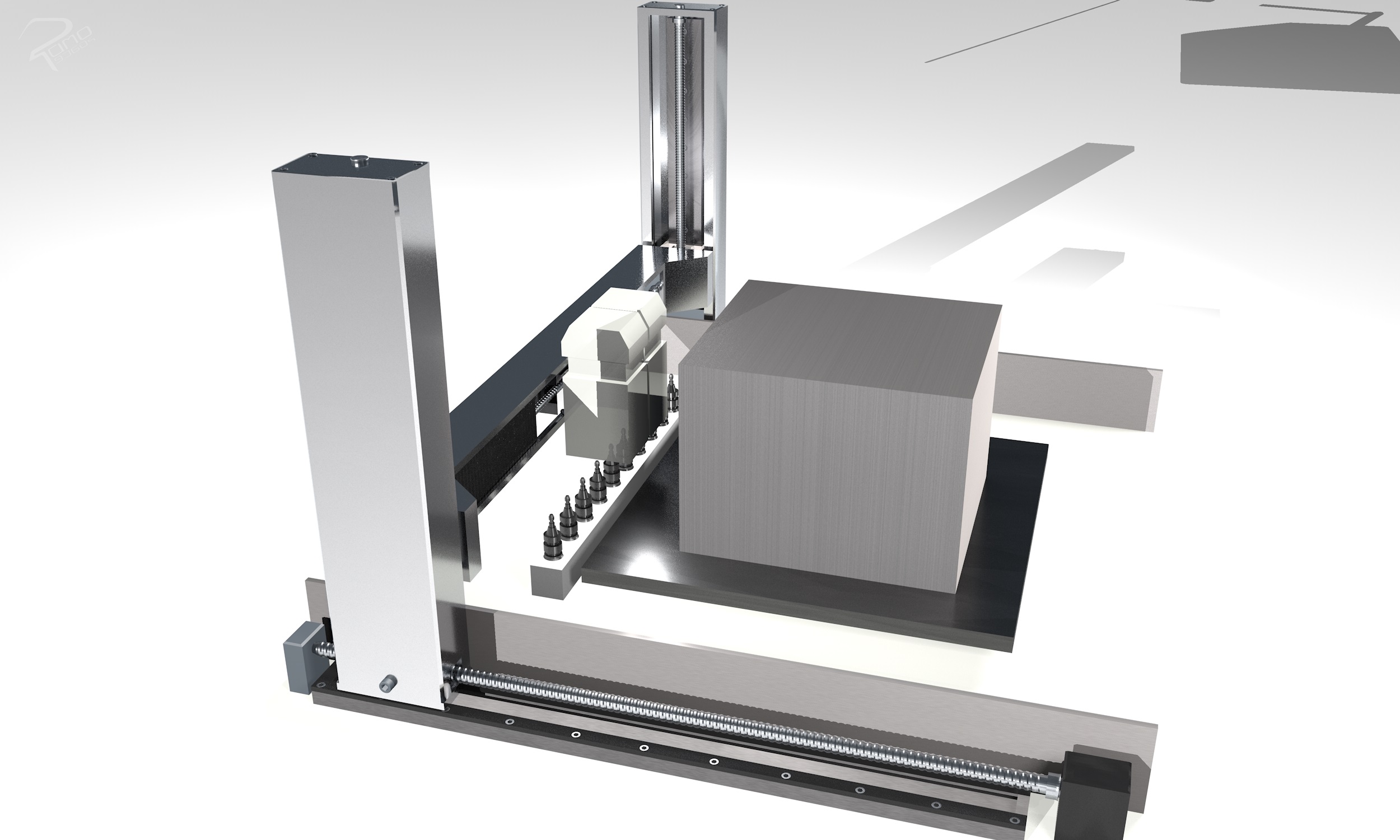
The advantages of this rack and guide system is the easy construction, the possibility of extension of the working surface and the easy removal of the products. The working surface can be extended as desired on the x-axis by extending the guide rail and the spindle.
Frame Concept 2
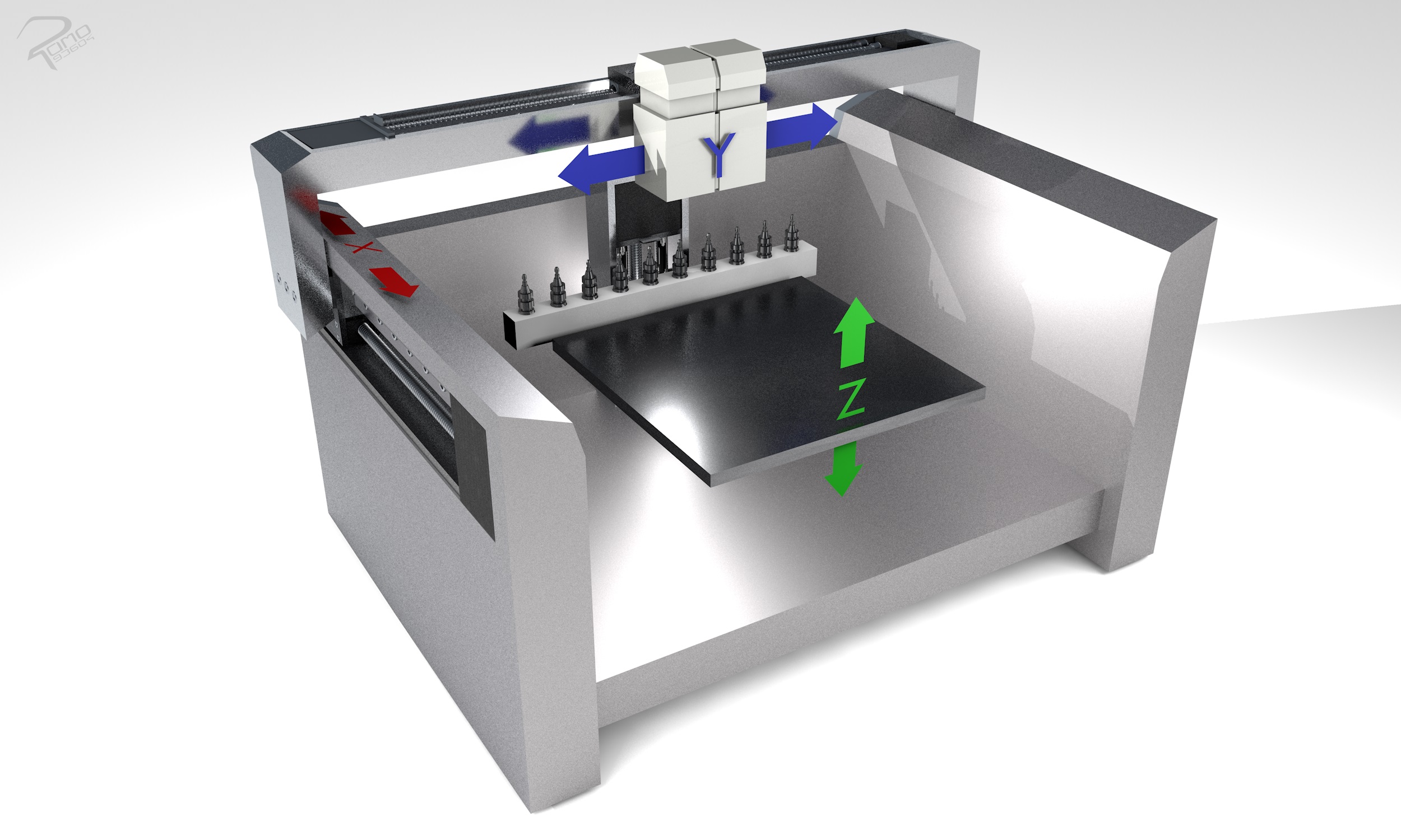
The second concept has a guide axis system and frame of an overhead gantry design in a slightly closed housing shape with the difference that the work surface is guided to the machining head. This results in one workpiece axis and two tool axes. The guide axis system and frame consist of three walls. The two parallel walls contain the xaxis guiding systems for the movement of the cross beam. A stand for the Z-axis guide system, which moves the work surface and the toolbox in the z-direction, is attached to the foundation and to the rear wall. The z-axis guiding system includes a crossbeam arm that is connected to the work surface and this enables movement of the workpiece in the z-axis direction.
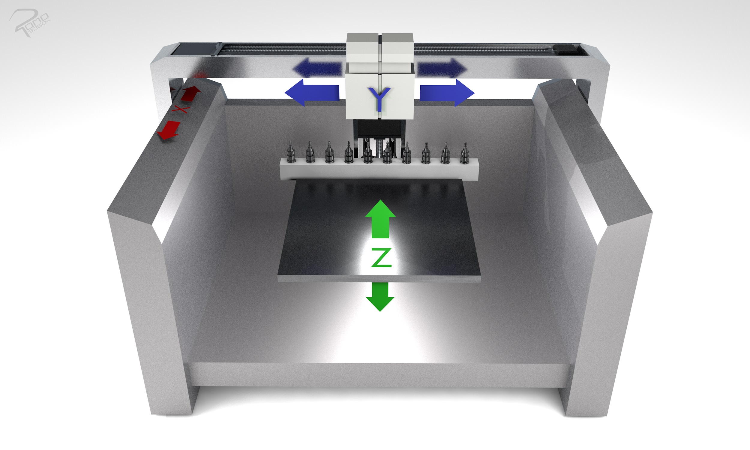
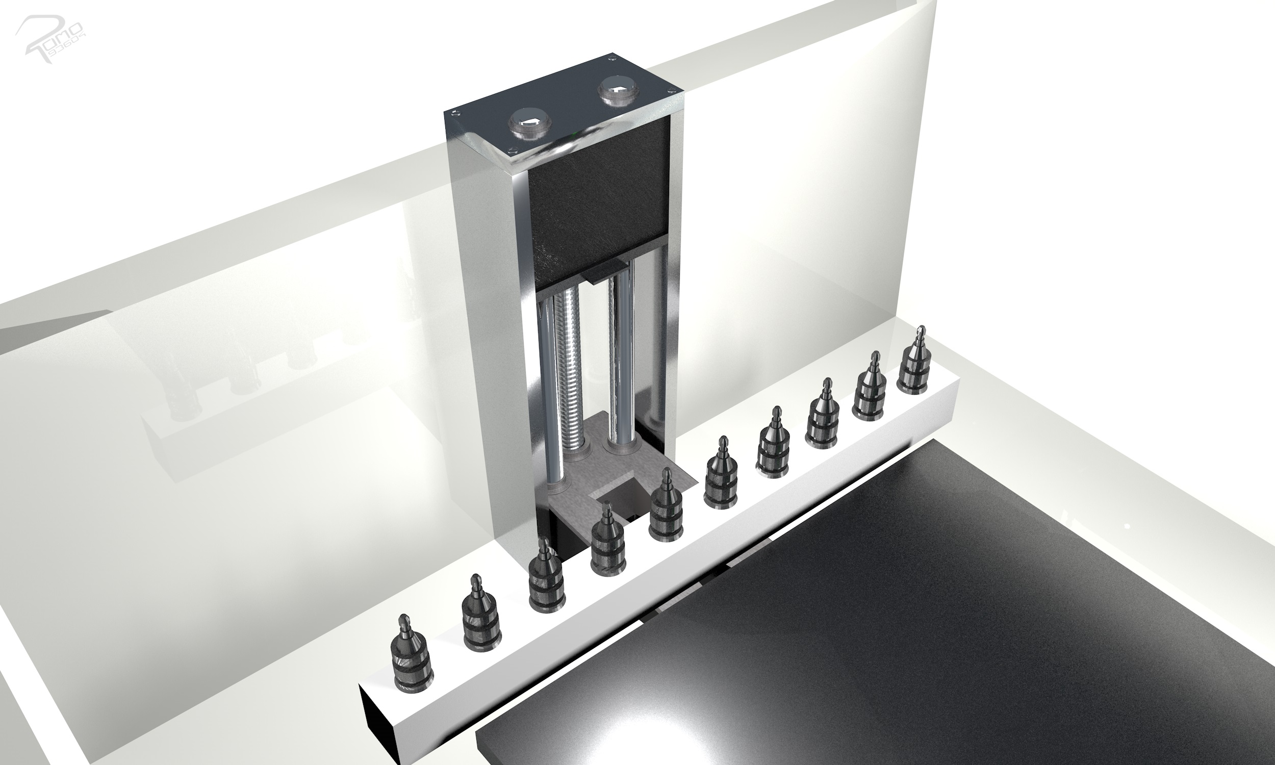
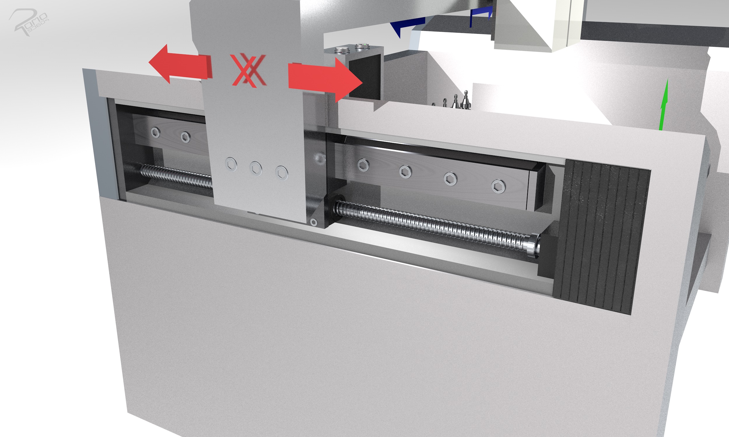
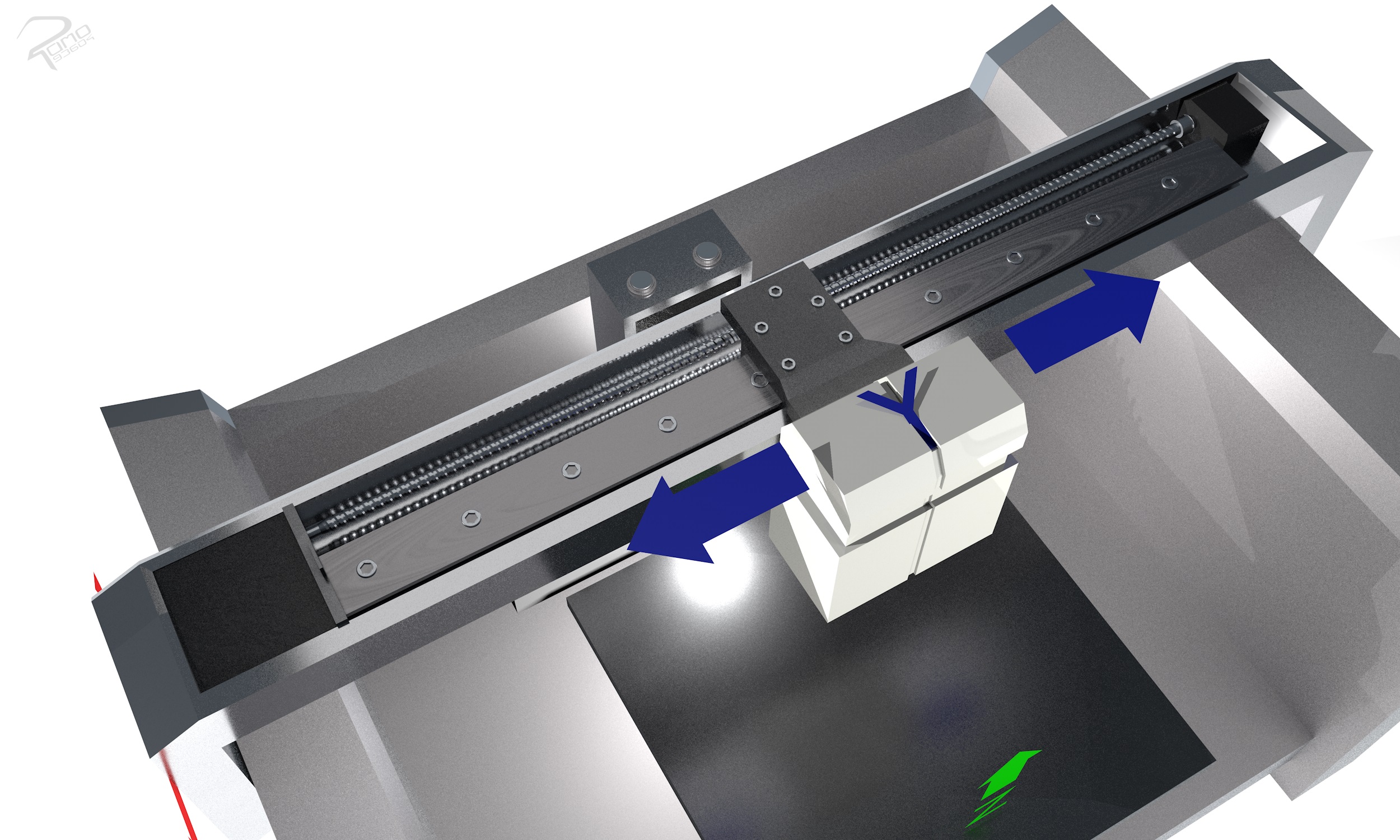
An advantage of the concept is the design of the system, which offers possibilities to close the system with a housing. In addition, x- and y-axis guide systems are protected from direct contact with cutting material by the tool, since the guide system openings are positioned in the opposite direction of the work area. Furthermore, the x-axis guide housings with their components can be removed for maintenance, repair or replacement.
Frame Concept 3
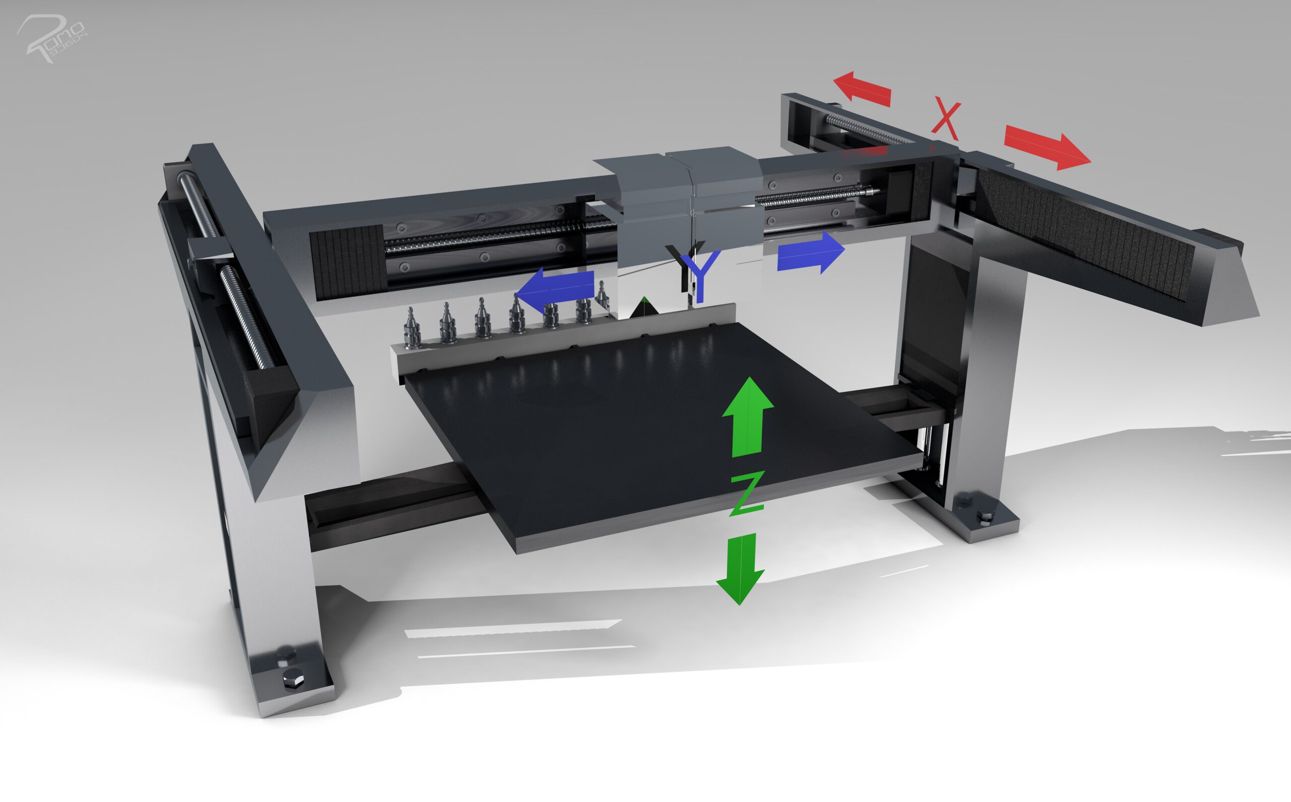
The third concept has similarities in the form of an overhead gantry design (portal design). However, the concept differs from the overhead gantry design in the movement of the z-axis. In the overhead gantry design, the head can move in the z-direction through the guide system. In this concept, the z-movement is generated by the sliding table, which is guided on both uprights. Thus, the concept consists of two tool axes and one workpiece axis. With this design, the column must be rigid and not allowed to move. If it is possible to fix it to the base, a crossbeam must be connected to the feet of the two uprights to increase rigidity. In the case of high forces and speeds, an additional crossbar can be added above the crossbeam connecting the two uprights.
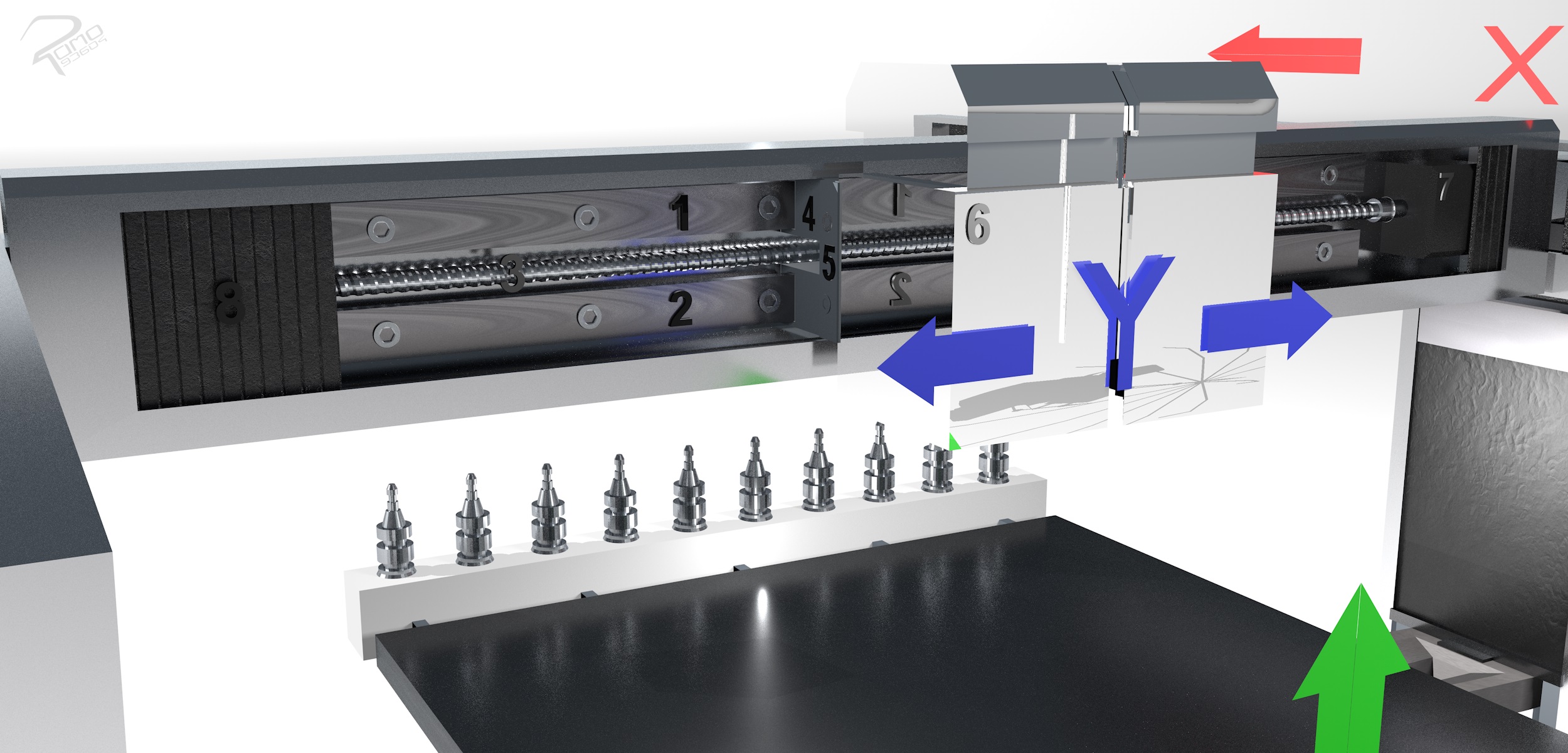
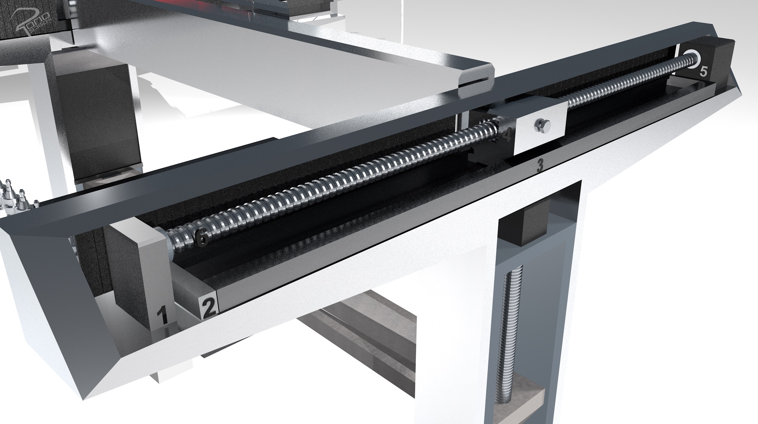
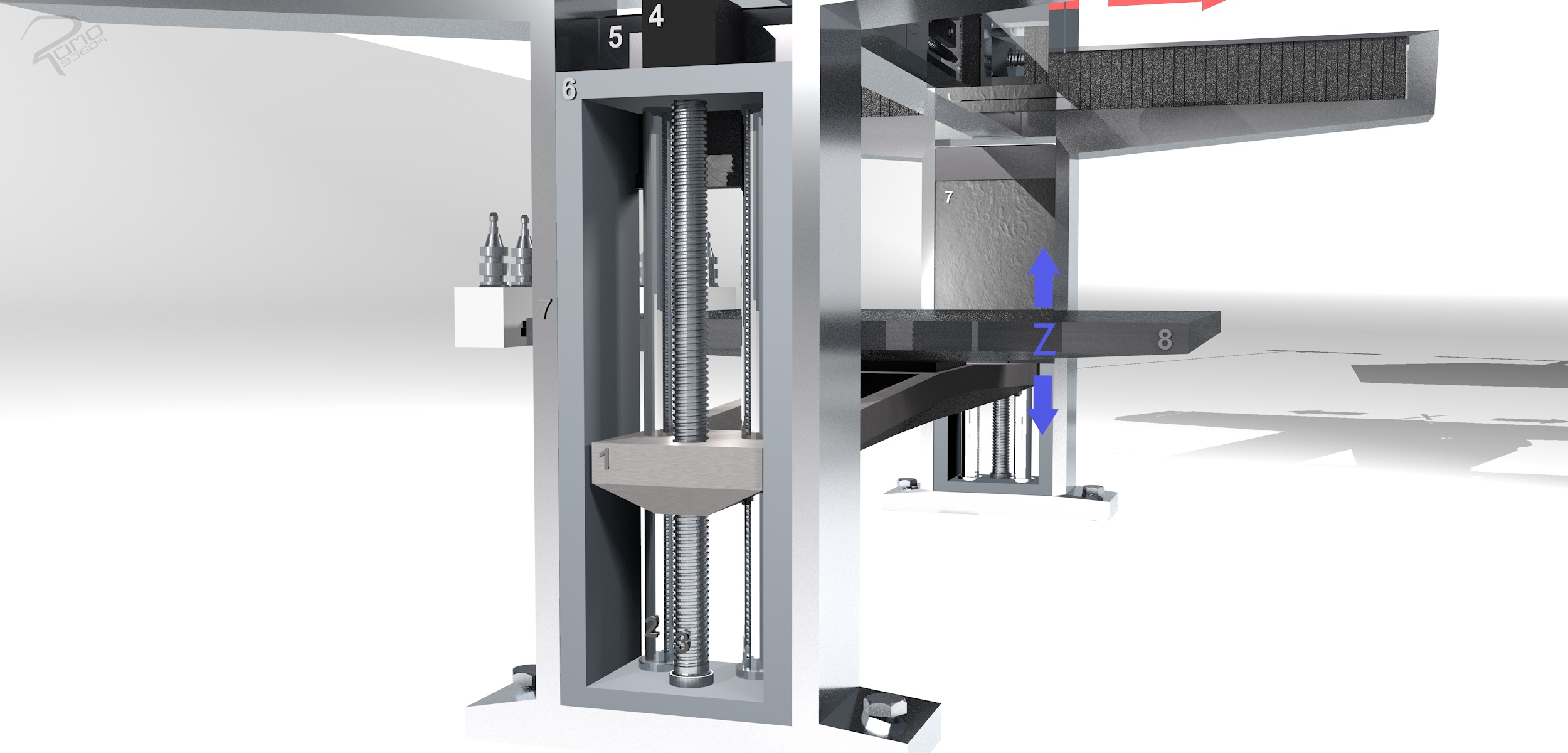
The third concept has the advantage of picking up and processing large masses. Due to the construction and the mounting of the machine on the floor, larger forces can be absorbed. The operating height is also an advantage, due to the mobile work table. When setting down and removing the workpiece, the crossbeam can be moved to the side and the work table raised. All guides and spindle are protected from chips and dirt.
Frame Concept 4
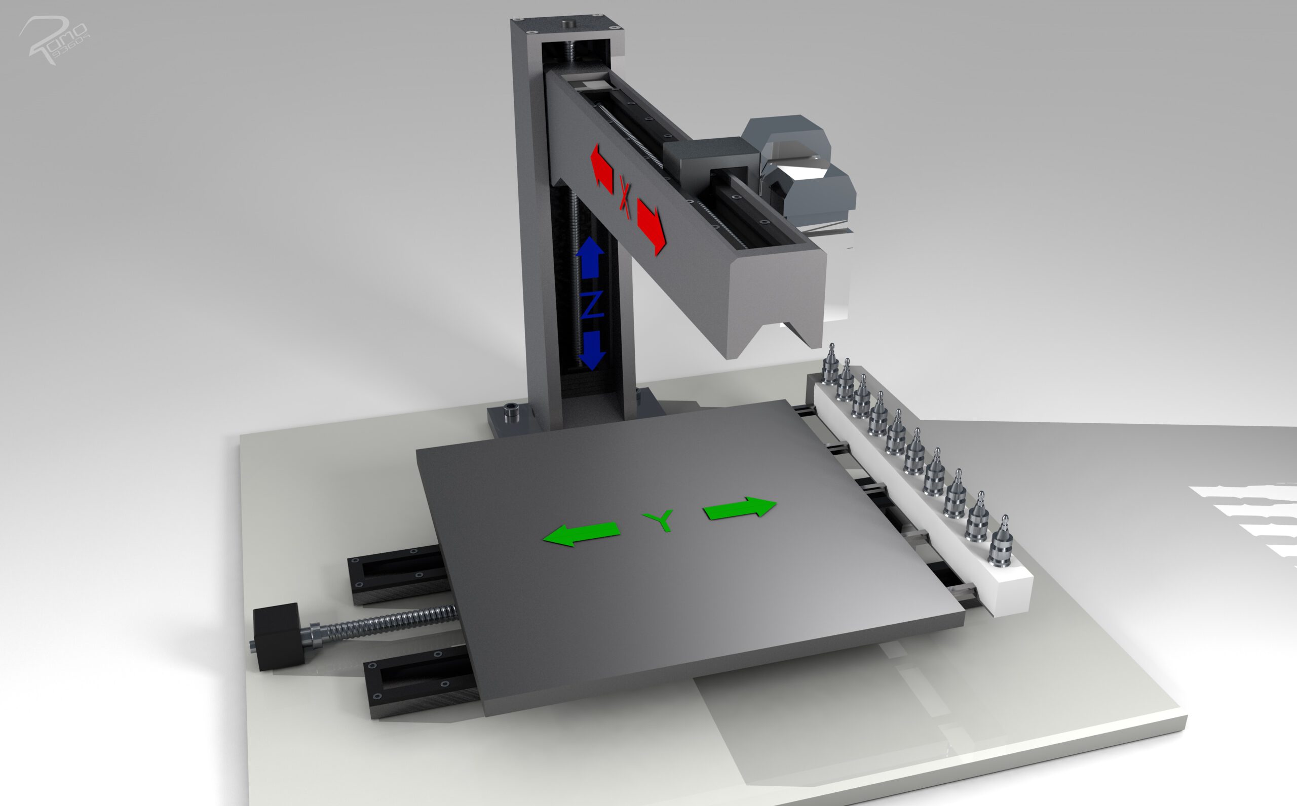
The fourth concept has the design of a cross-bed construction with two tool axes and one workpiece axis. In this variant, the column stands rigidly and is fixed to the foundation with 4 screws. The extruder and milling unit are held in position with a beam and a stand. The movement in the x and z axis are guided by the stand and beam. Movement in the y direction is guided by a separate guide on the foundation. This design differs from the other concepts in the number of stands. With this concept, only one stand is required. The head with the extruder and milling unit is guided laterally on the beam. This is connected to the guide carriage with a mounting rail.
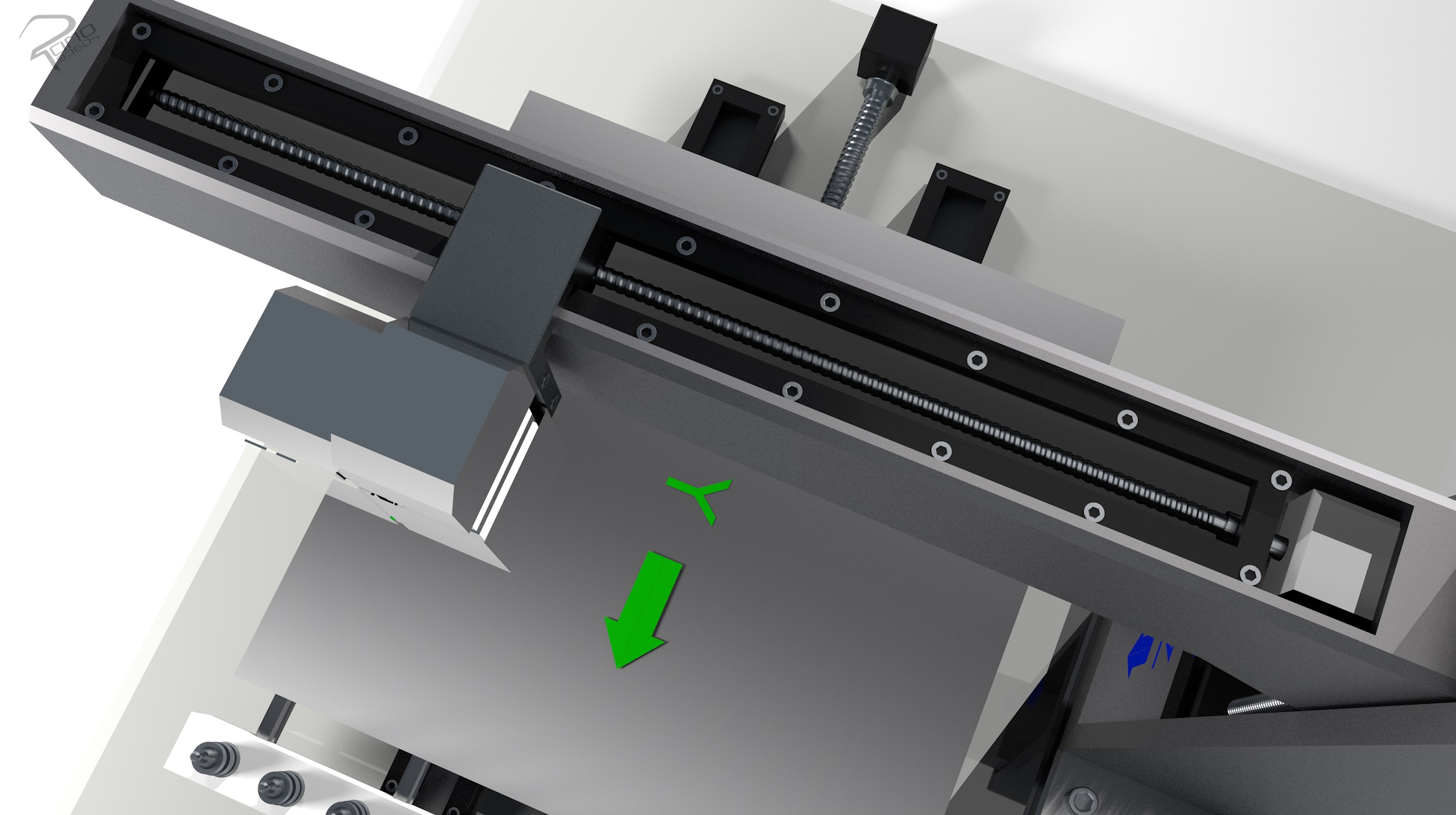
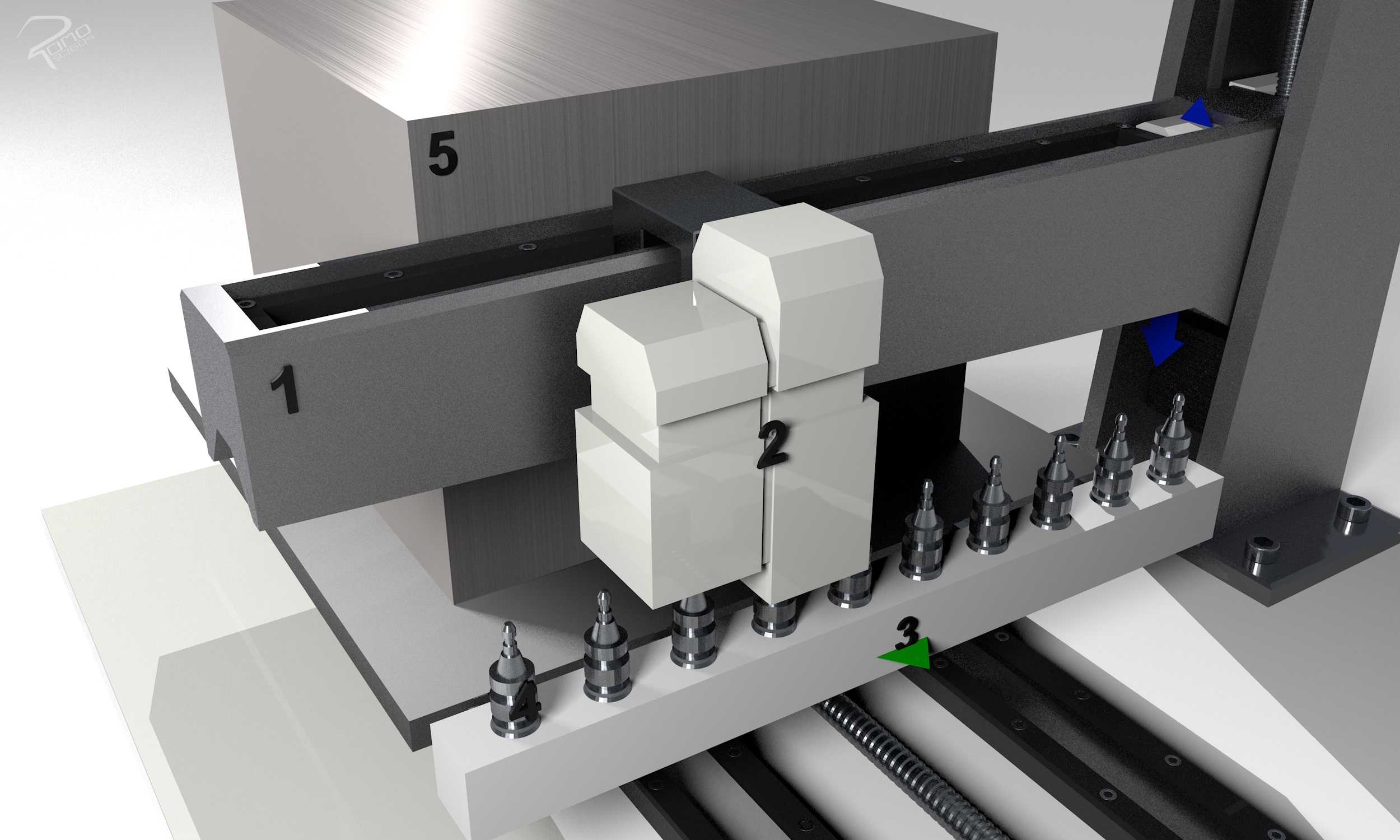
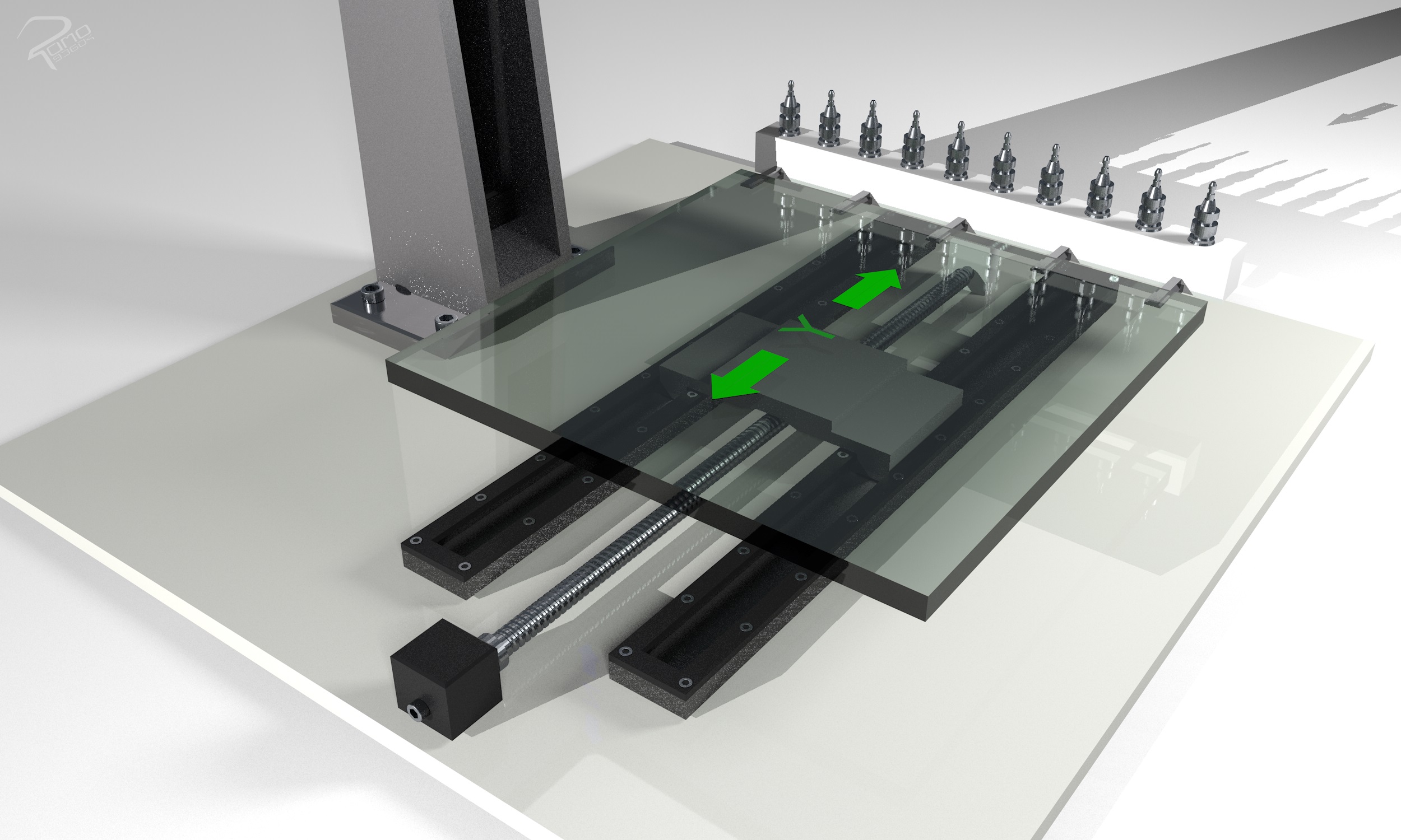
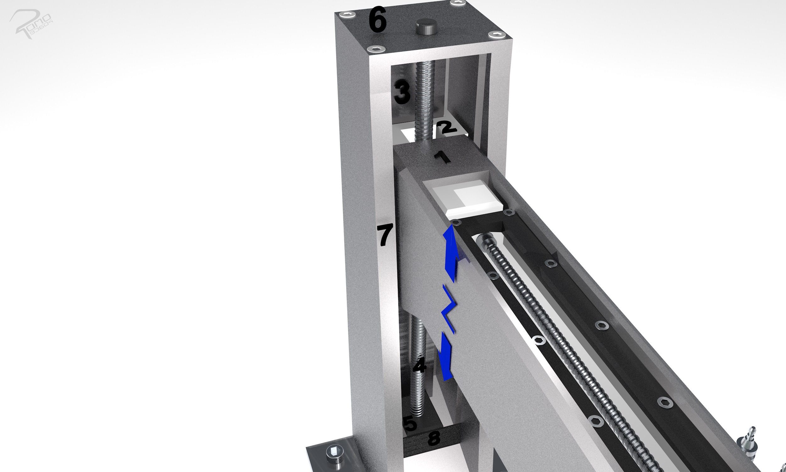
The concept requires fewer components and has a small installation space due to the single stand design. The worktable is movably mounted and can be moved to the side during removal so that the stand with the crossbeam is no longer above it. This facilitates the removal and setting out process. The work box is easily accessible. The guide in the x-axis is well protected from chips and dirt by the upper laying and can be additionally protected with a link guard. The z-axis can also be extended with a link guard.
Exdruder and milling unit
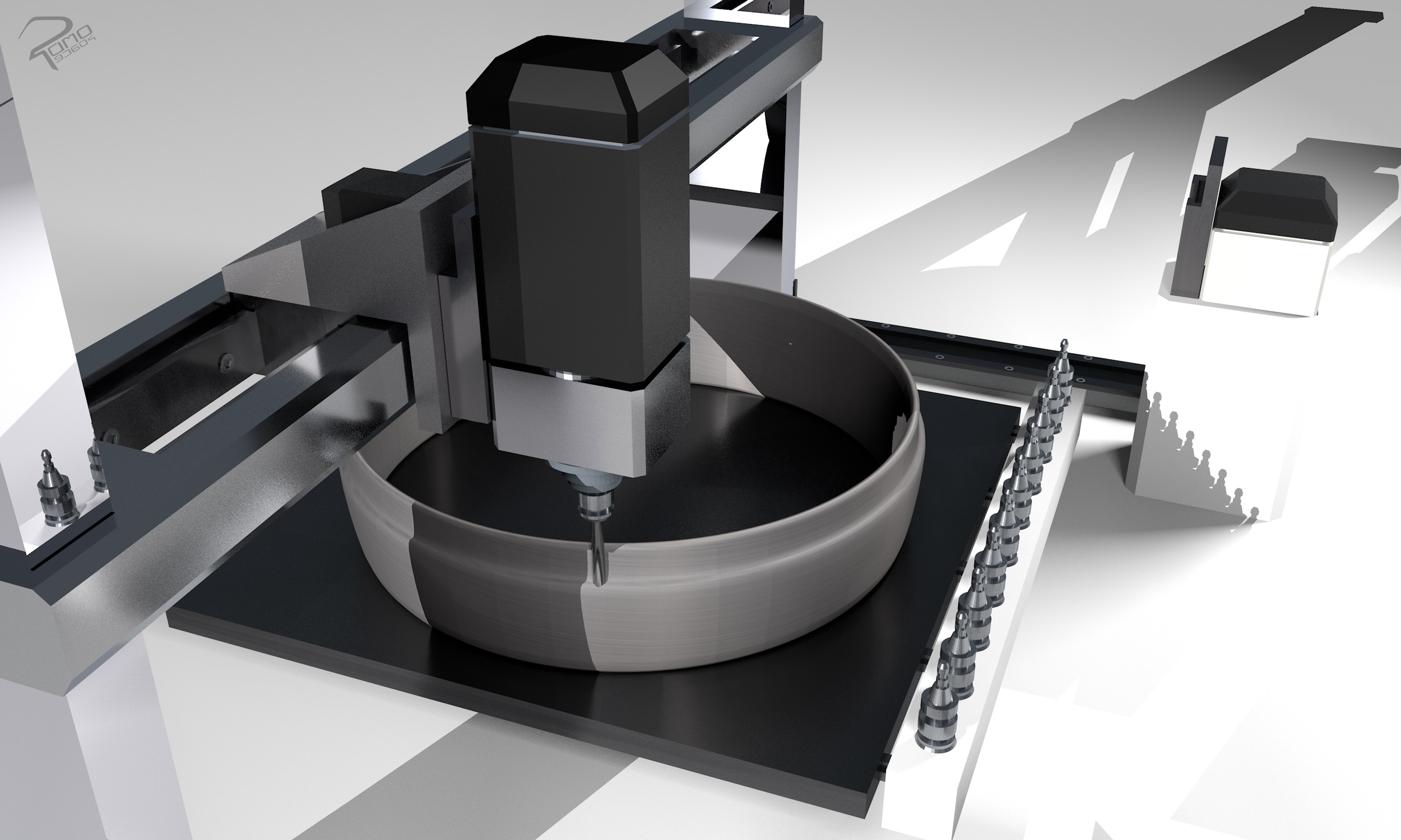
The following section presents several concepts for the design of the exdruder and milling unit. The key points of the design were the positioning of the components, design, construction and operation in general.
The following five concepts were developed:
- The first concept of the head unit with the milling and extruder function provides for the milling unit to be fixed firmly to the carriage with an automated tool clamping device. In this case, the milling unit can machine the workpiece and change the tool as usual. In addition to the tools, the extruder unit is added as an exchangeable tool.
- In the second concept, the milling and extruder unit is divided onto two carriages. However, both carriages are guided on the same rail in y- or x-axis. The carriages are equipped either with two different drives or with a coupling system that connects and disconnects the carriages with the drive. When using the milling unit, the carriage with the extruder unit is parked at the end of the guide rail.
- The third concept is to position the milling unit and the extruder unit separately on two guide systems. The operation of the concept is similar to the second concept with the difference that the extruder unit does not have to directly share a guide rail with the milling unit. When the milling unit is running in the machining process, the extruder unit with the guide system is parked in an undisturbed area.
- The fourth concept is based on a linking system that couples and separates the heads with the guiding system. This allows the heads to be exchanged automatically and used separately. Only one guide system is required here. The heads are each connected to their own carriage, which also contains a hole for a locating pin. A carriage for the y-axis is inserted in the crossbeam of the guideway system and bolted to the coupling system. is screwed to the coupling system.
- The fifth concept combines the extruder unit with the milling unit to form a head together on a guide carriage that moves on the Y axis. The height of one of the two processing units in the processing head can be adjusted. This allows the adjustable unit to reduce the distance to the work surface in the Z axis during the machining operation. When machining with the fixed machining unit, the movable machining unit is raised.
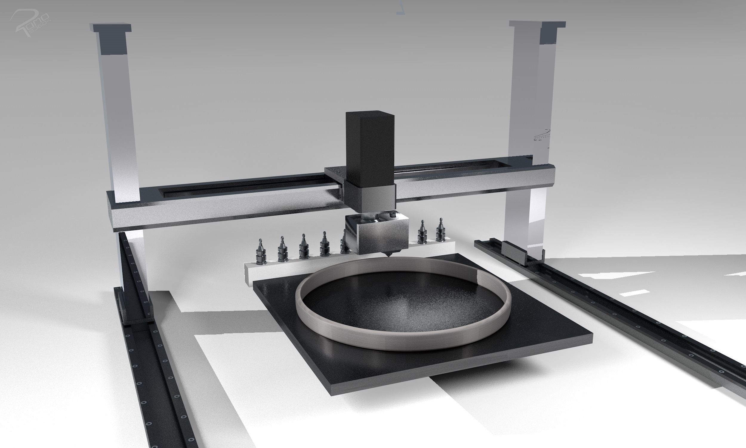
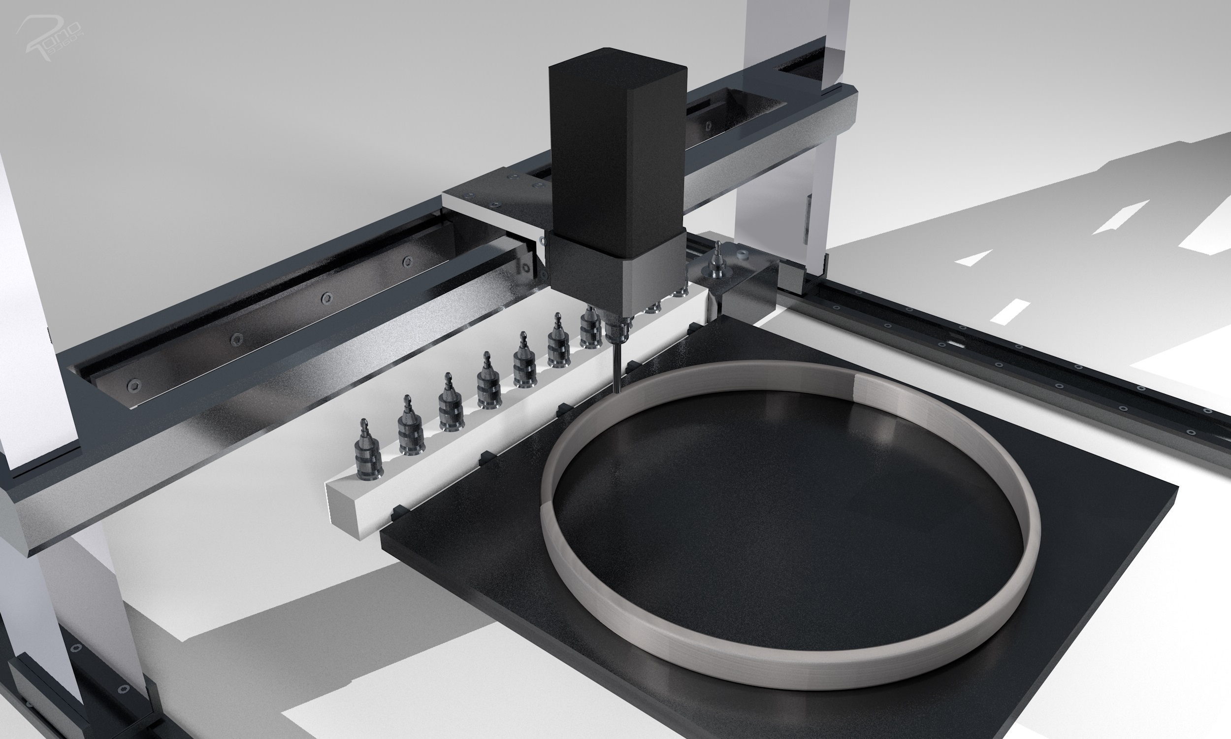
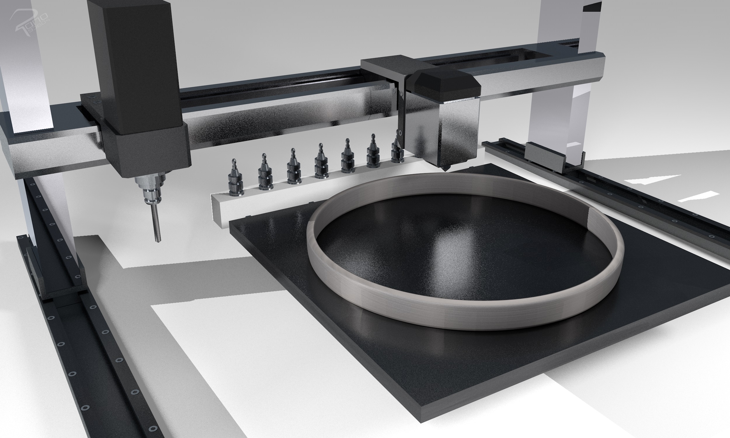
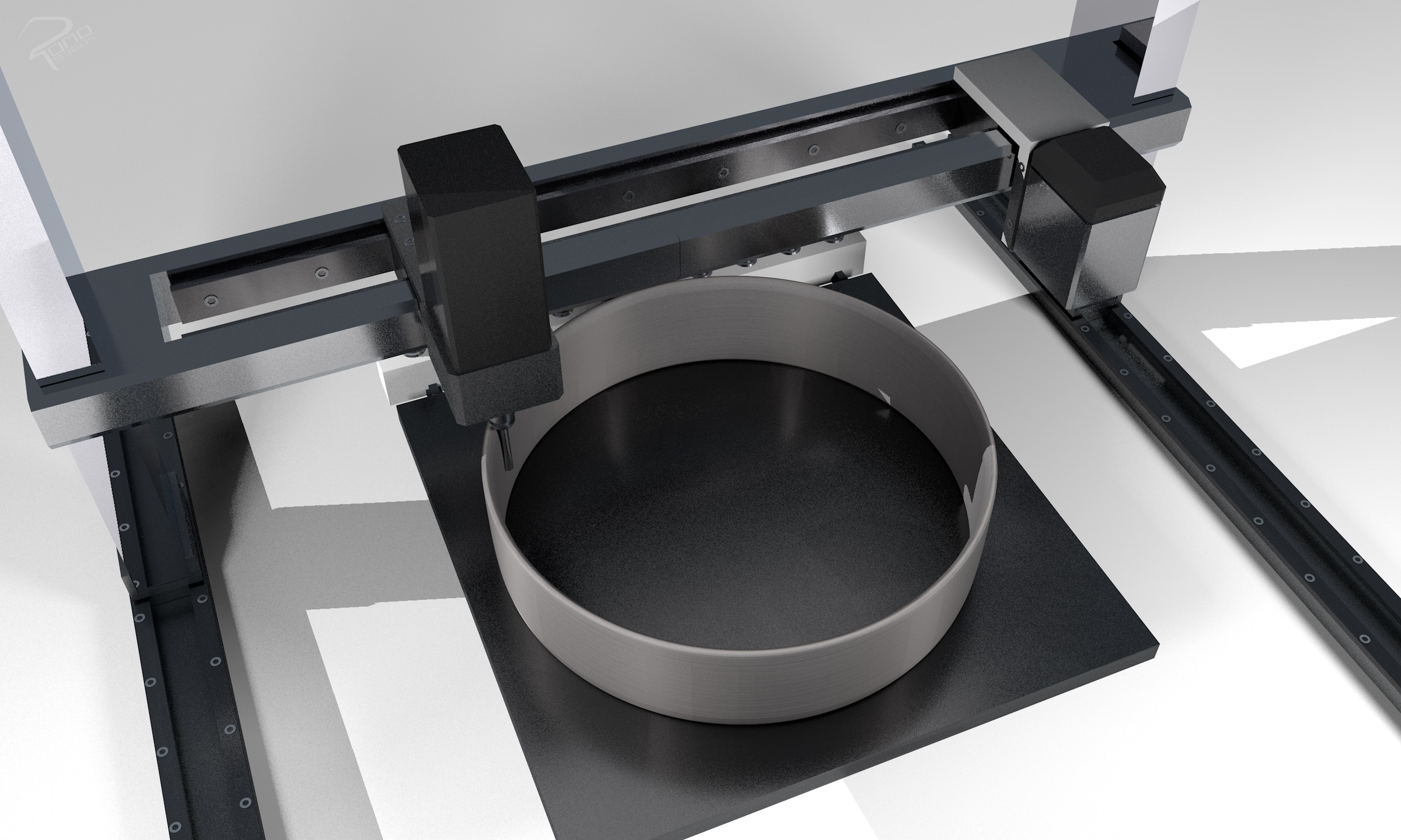
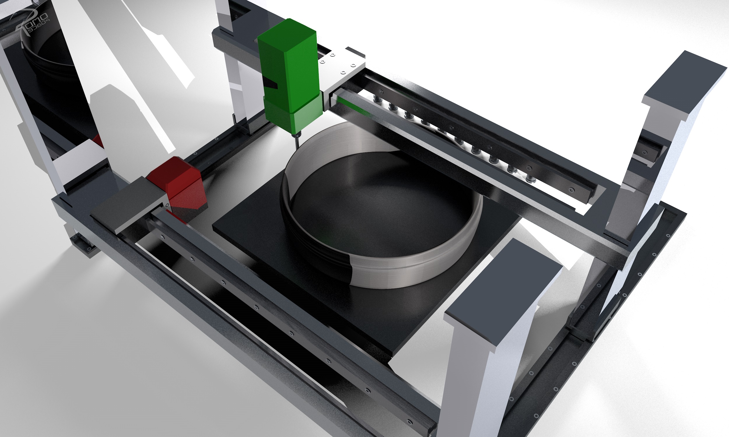
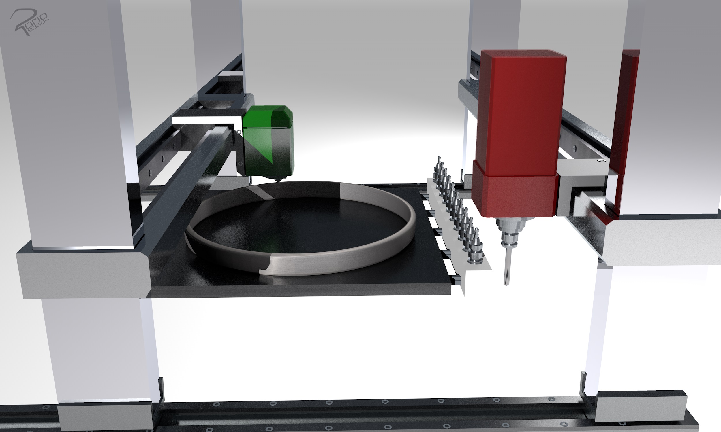
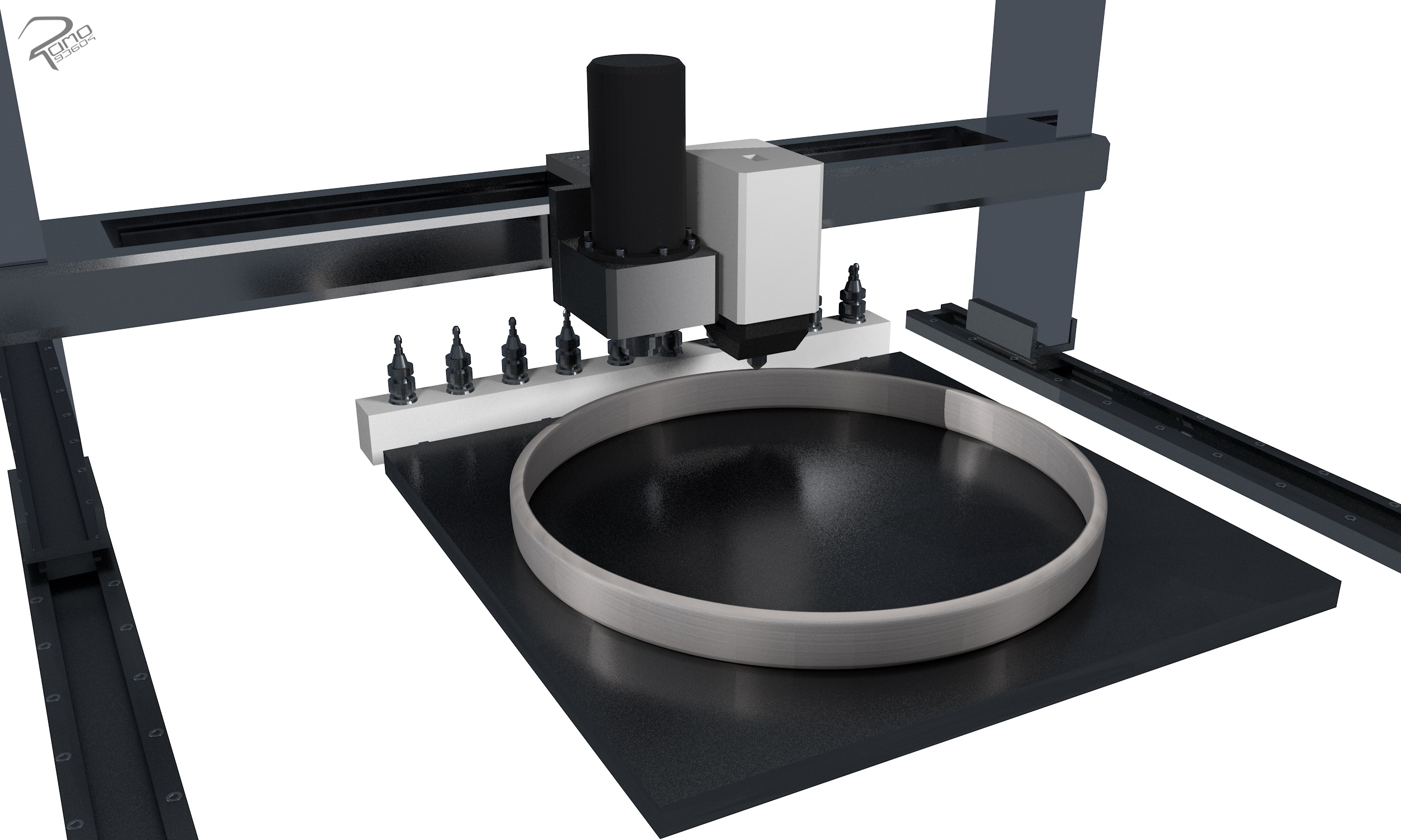
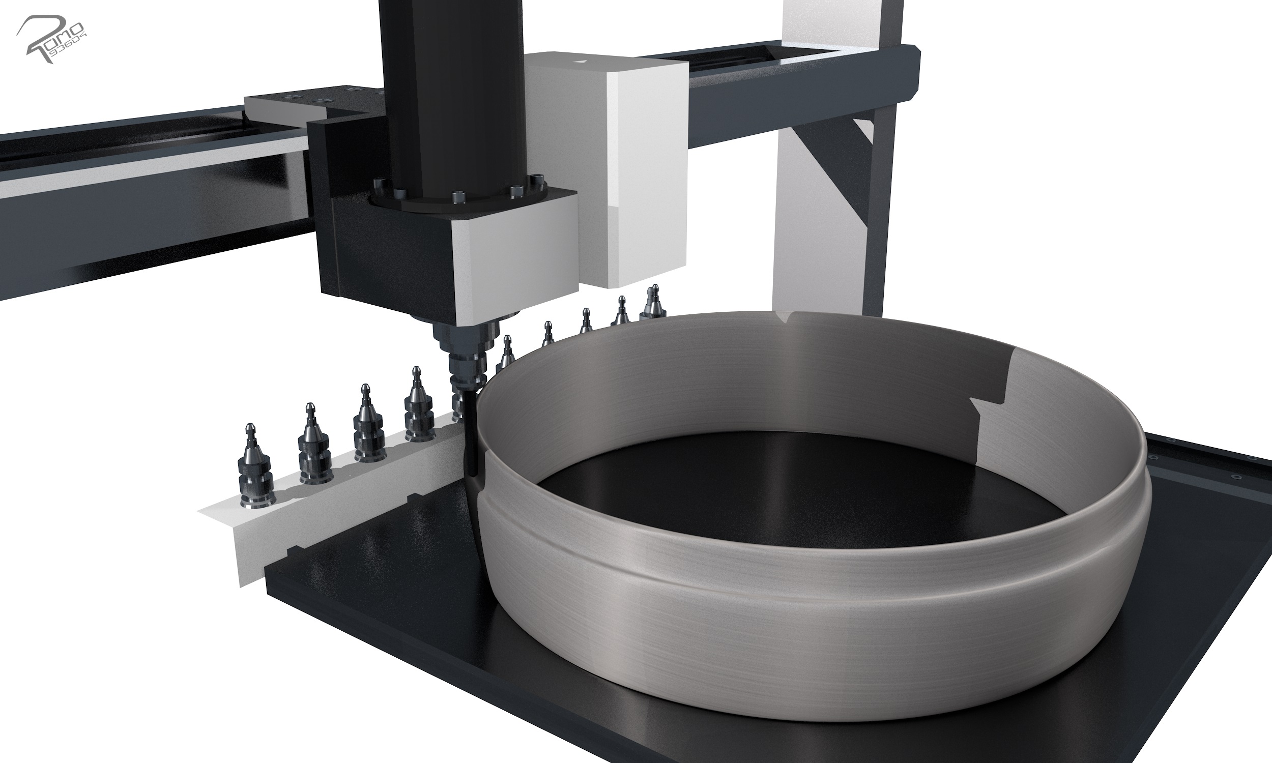
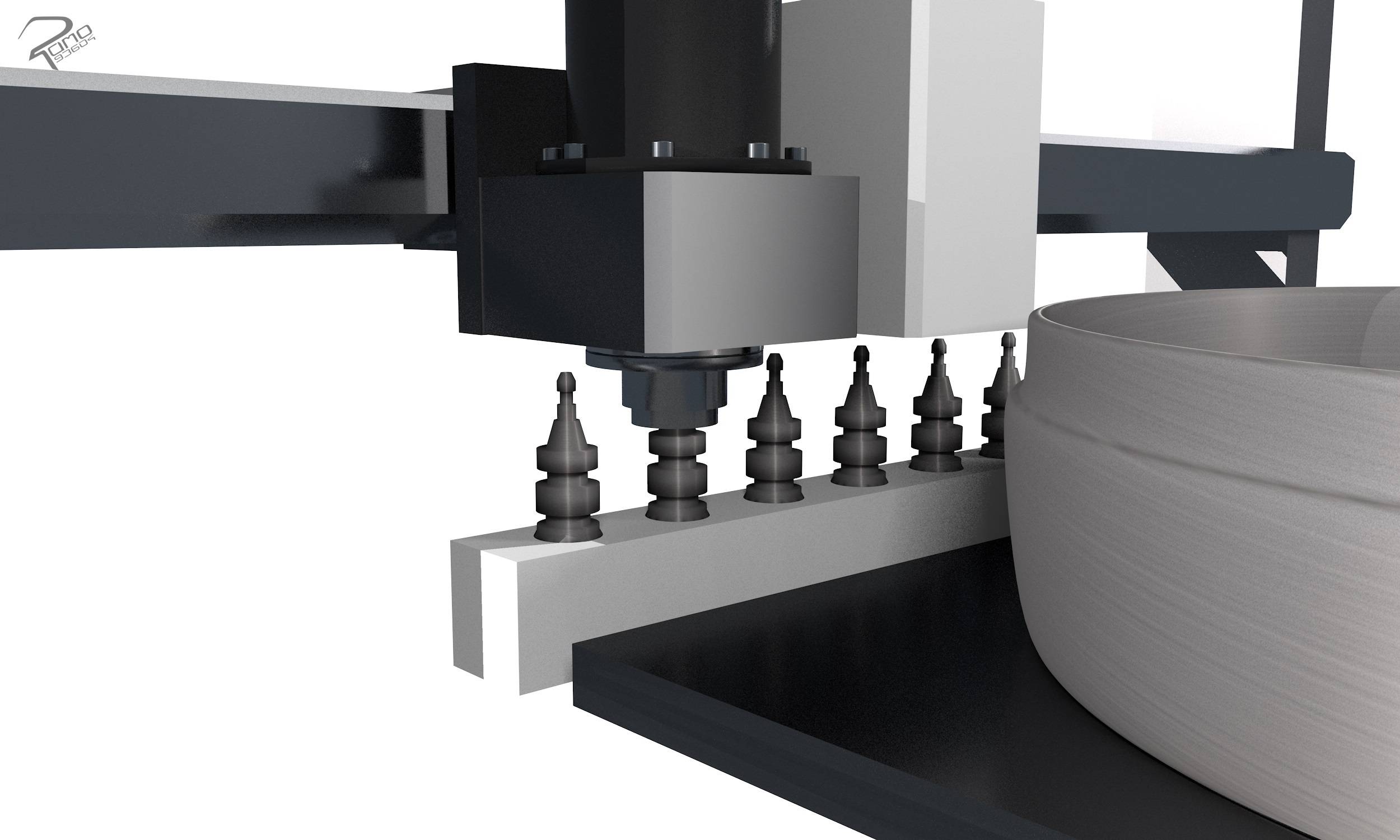

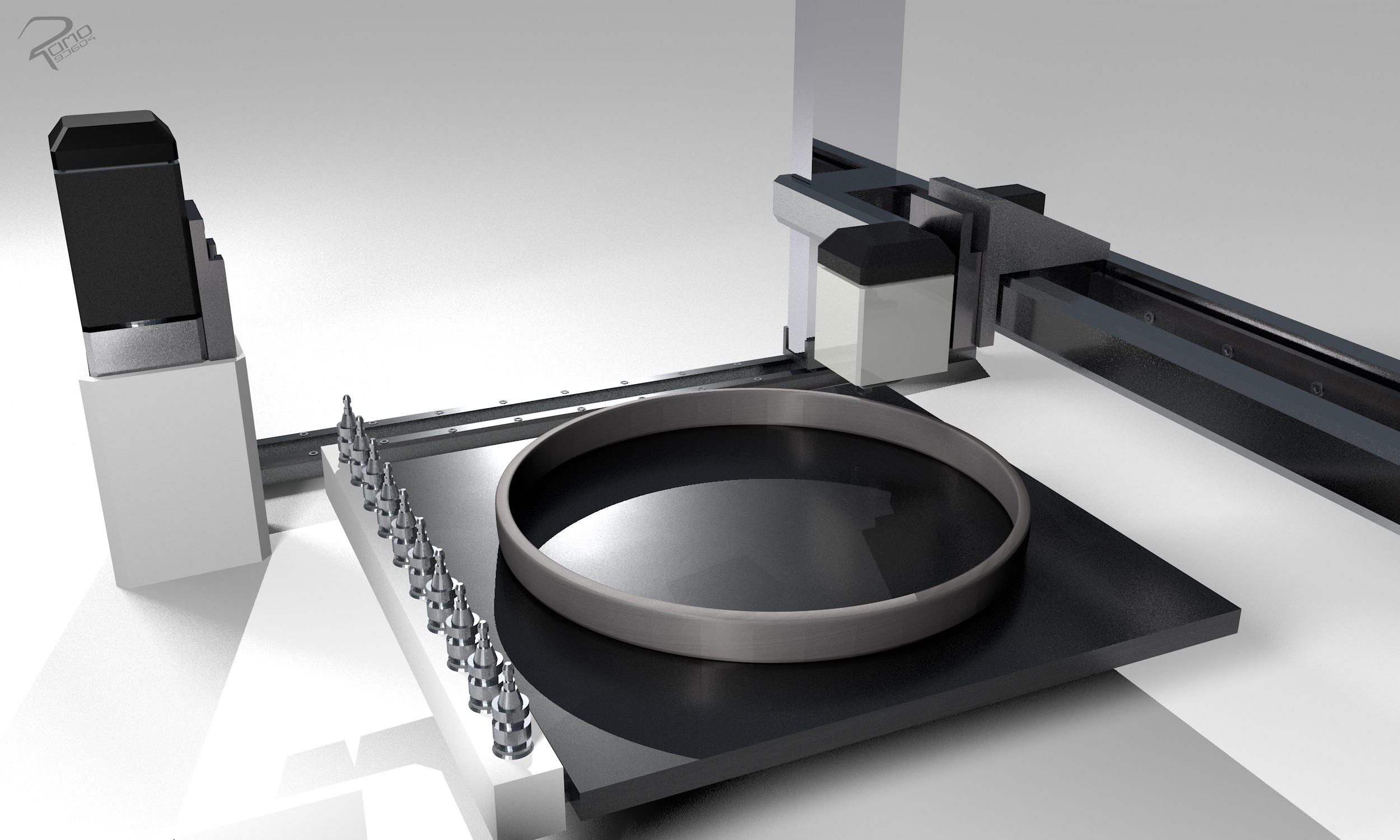
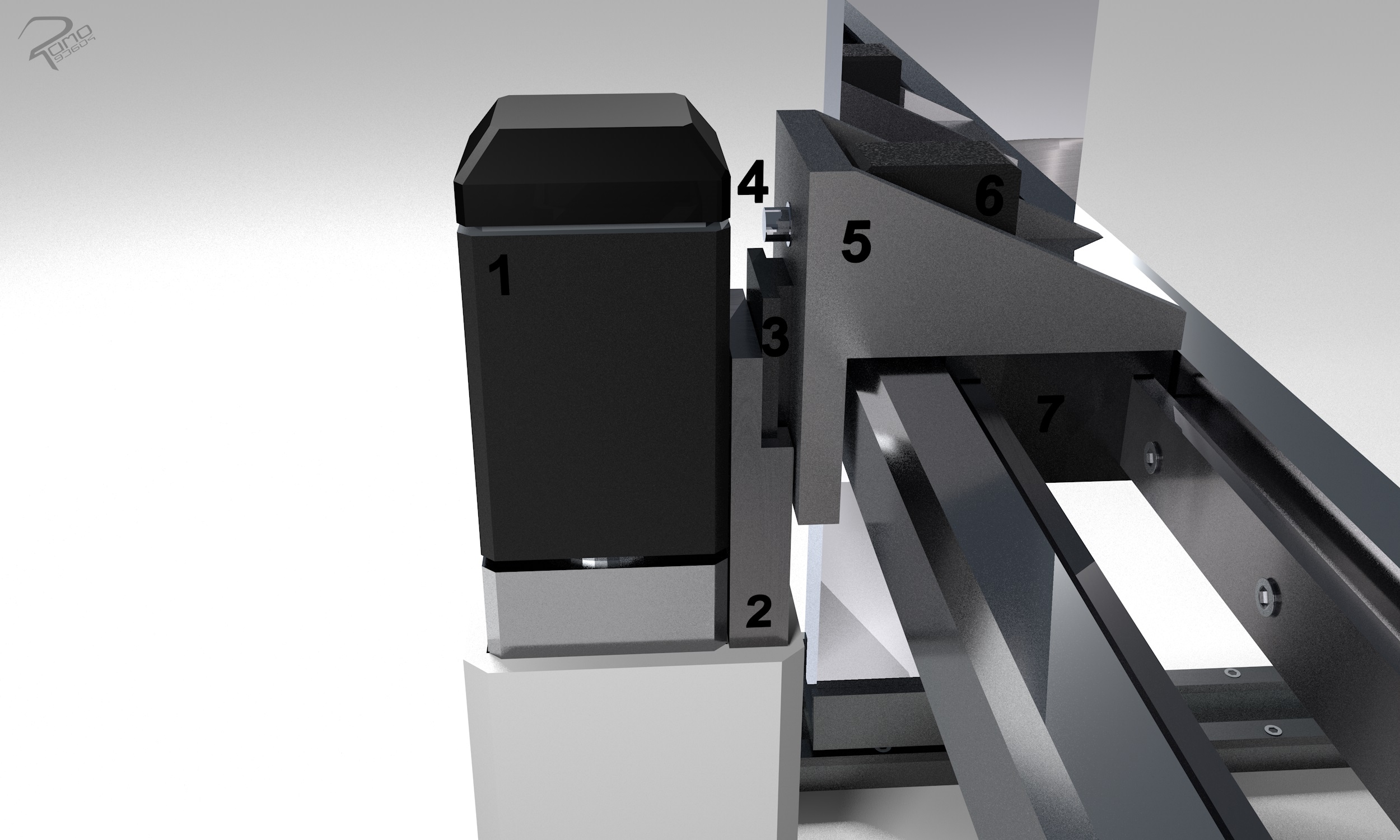
The redesign of the internal structure and functioning of the extruder and milling unit were not part of this work.
Work surface
In this section, solution/effective principles are presented for the work surface, which was developed with the help of the analysis and requirements of known systems.
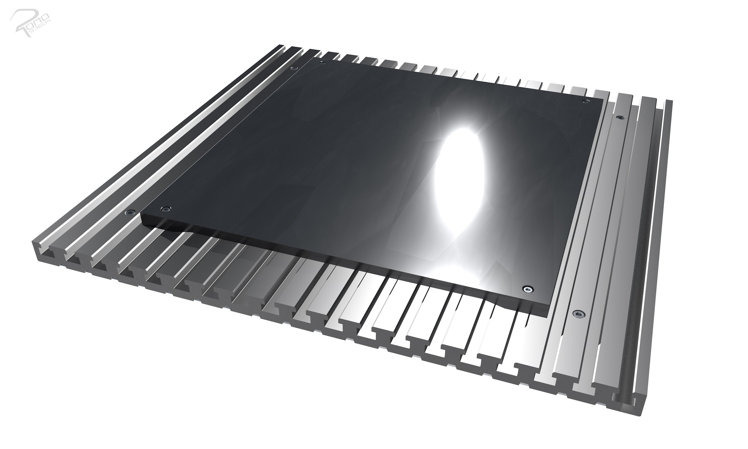
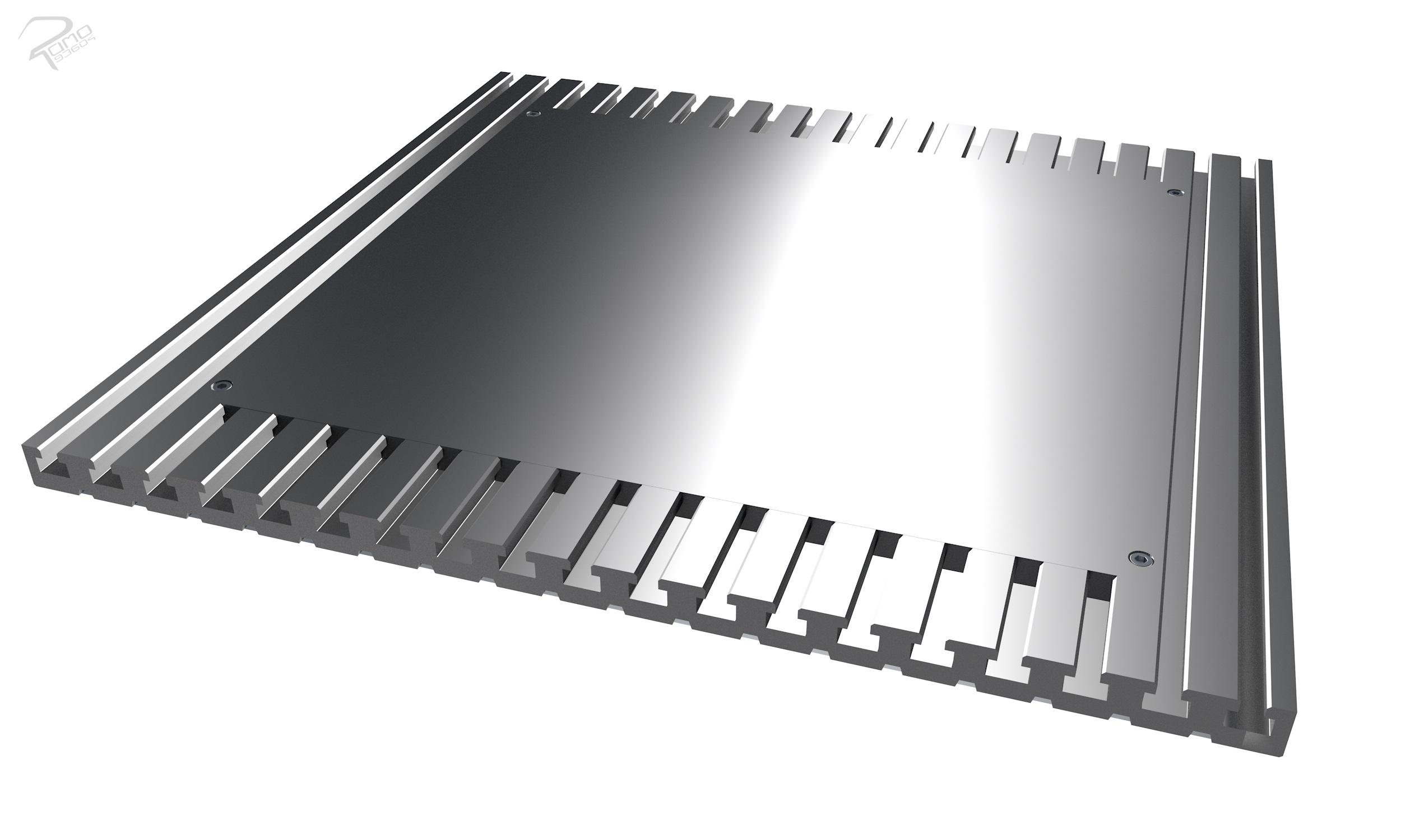
The work surface is used to hold the materials and the clamping elements. It is required for the FLM process and CNC milling. The working surface differs in its mode of operation for the processes. The task of the working surface of the FLM process is to receive the material, which is printed from the extruder head in the desired shape. The product quality and printing success is influenced by the working surface.
The following work surfaces can be considered:
- the first concept of the working surface unites the pressure plate with the groove system. Here, both plates are at the same height and consist of one part. In the center of the plate is the pressure plate, which is flat and smooth, and the edges of a T-slot shape.
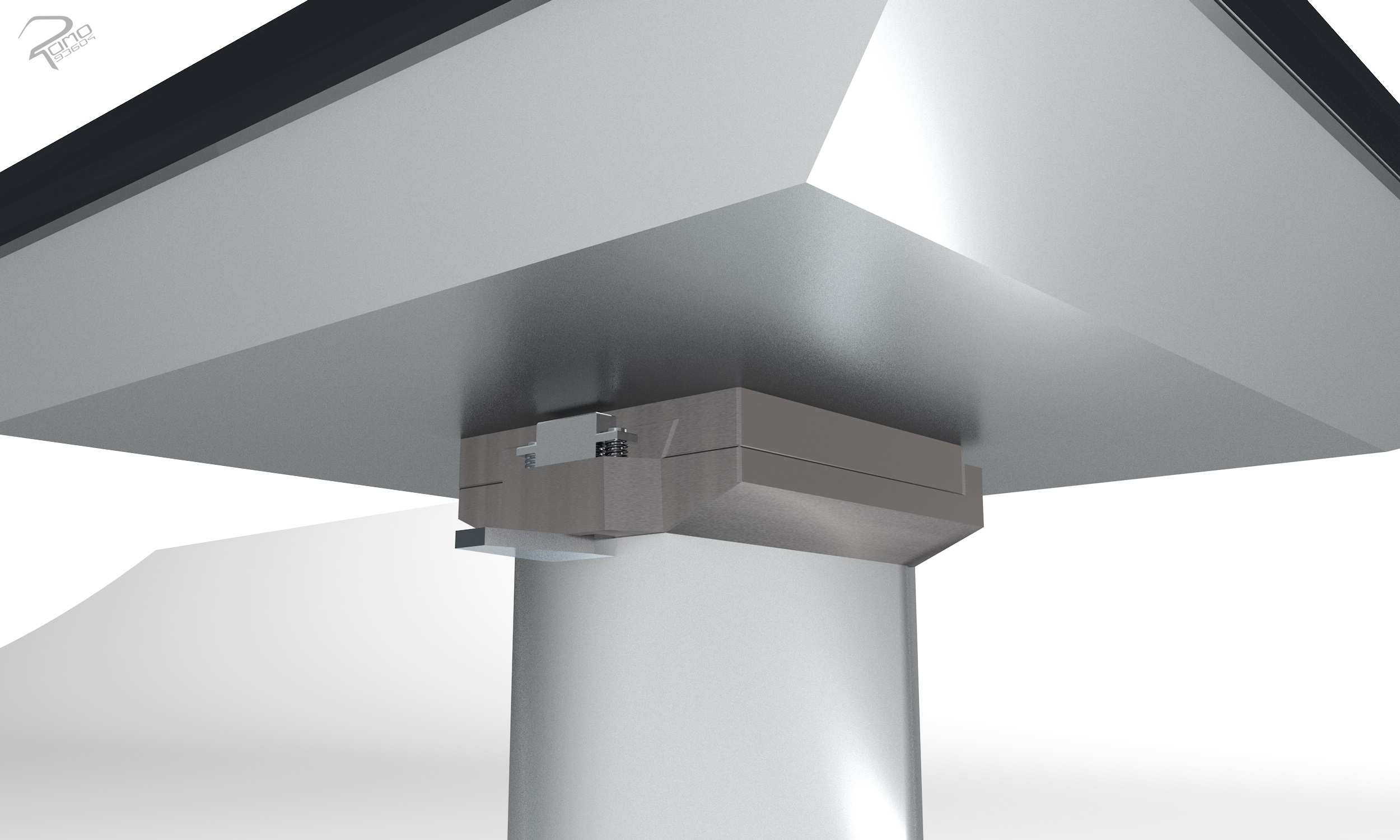
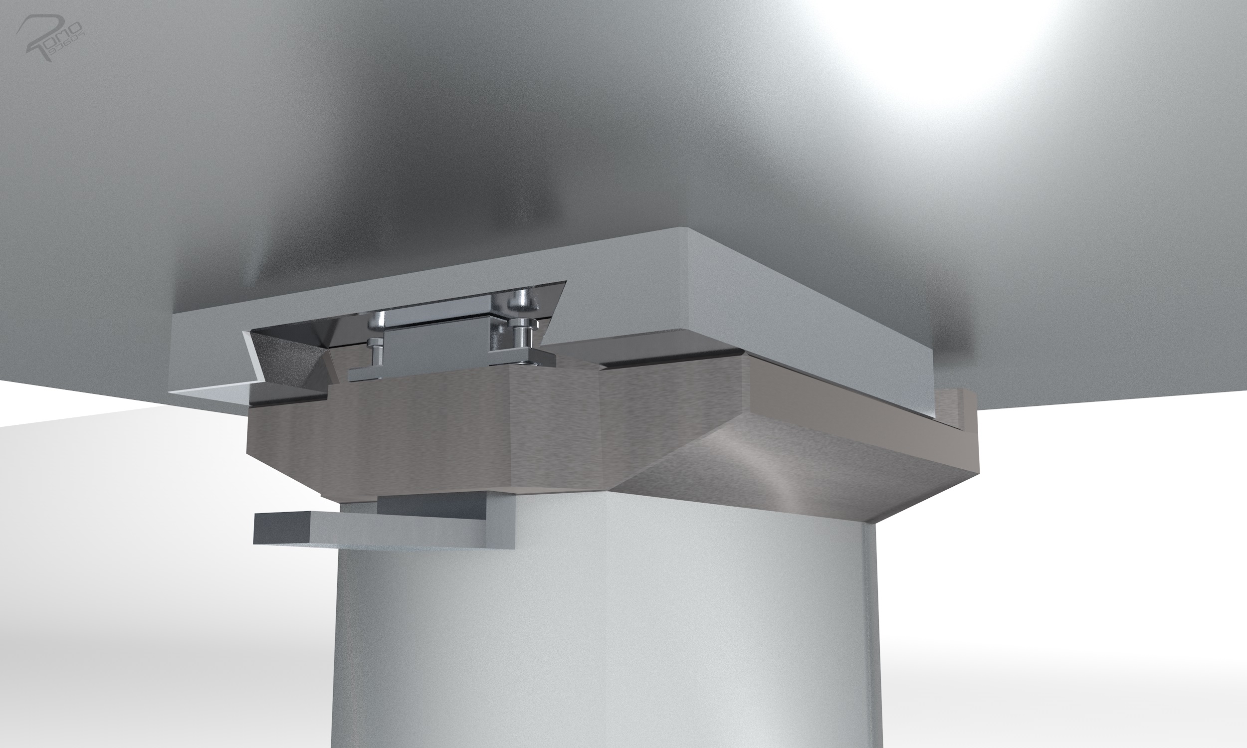
- the second concept is that a pressure plate is fixed on a T-slot plate. is fixed. The pressure plate is screwed to the T-slot plate with four screws and four sliding blocks. This allows the pressure plate to be fixed in different positions on the T-slot plate. Due to the separate shape of the two plates, different pressure plates can be used. Thus it is possible to use different sizes of pressure plates and with different functions, such as active leveling or with a heating function.
Clamping device for the workpieces
In CNC milling, the work surface is needed to fix the workpieces and clamping devices. In this section, the clamping fixture concepts for the milling process are presented.
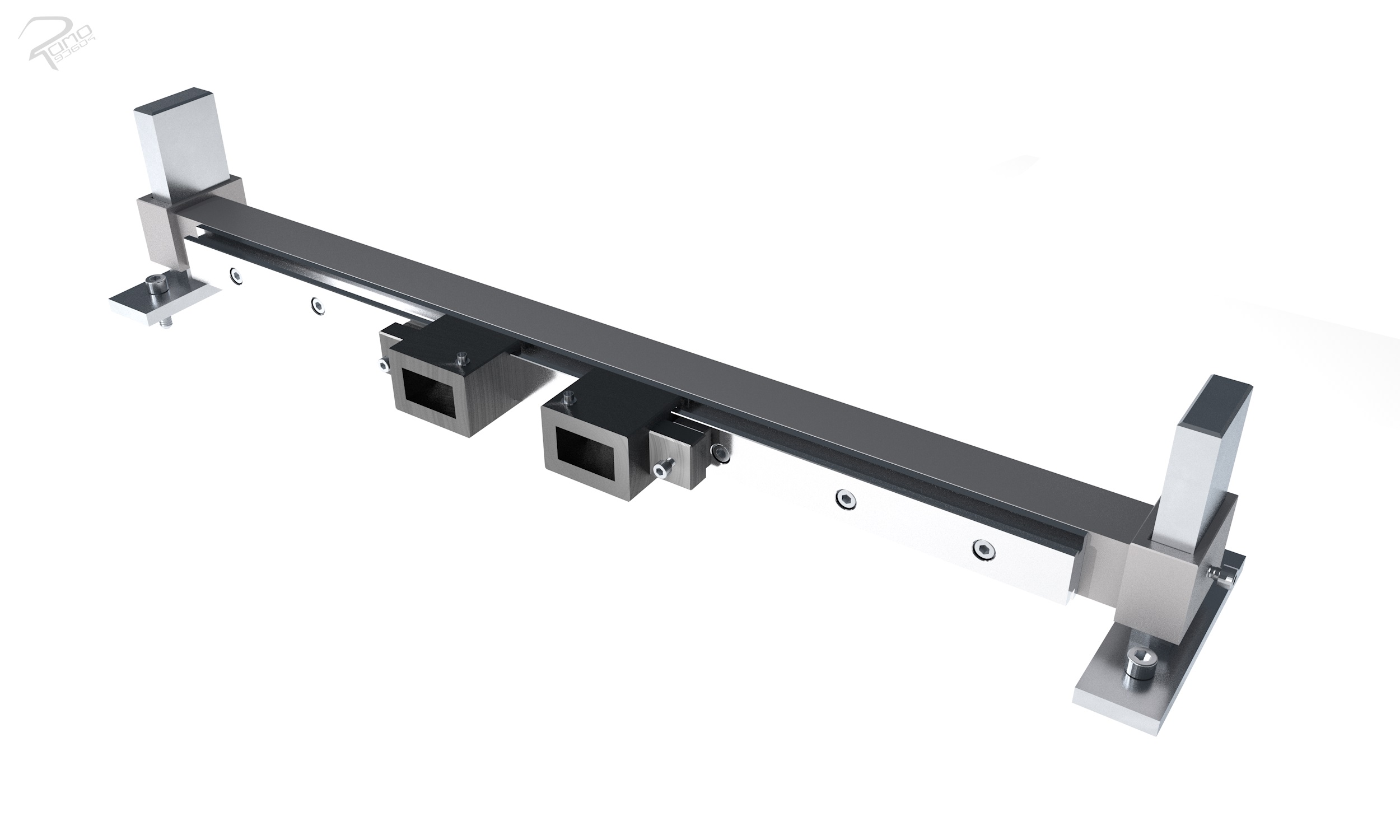
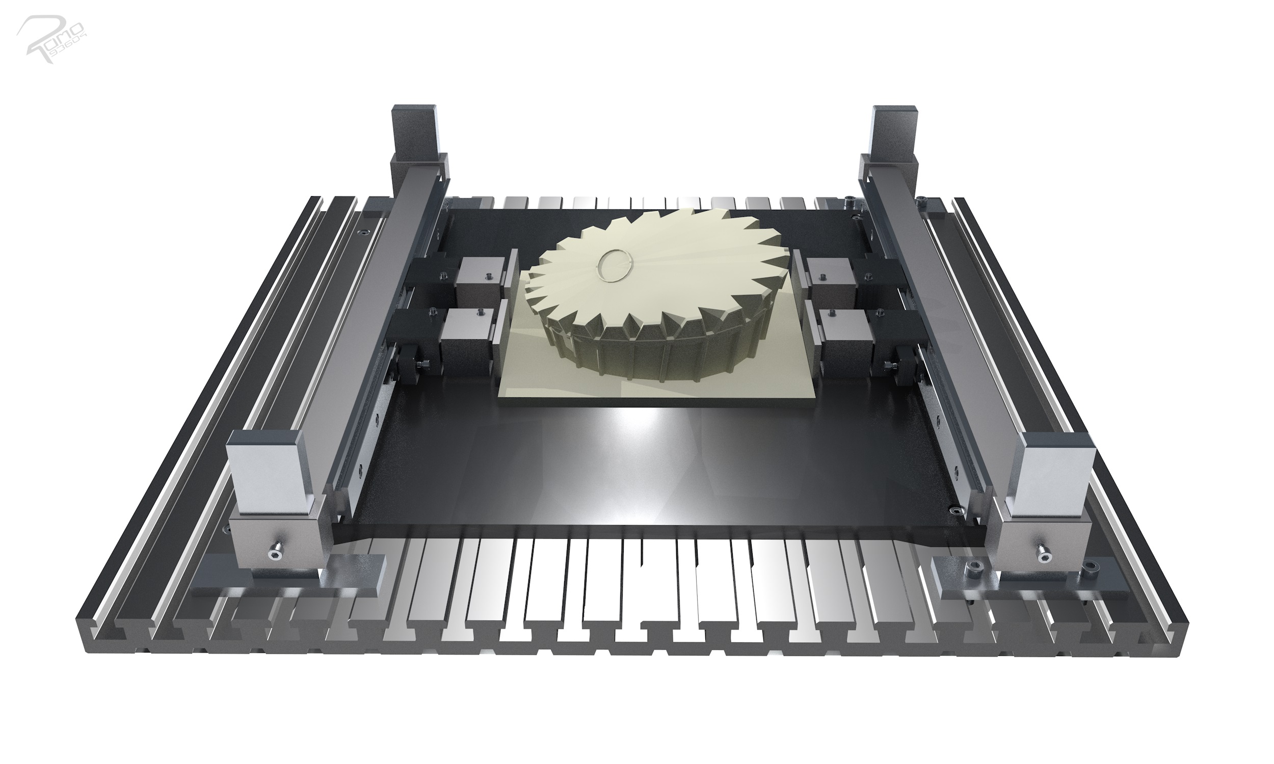
By using clamping devices, the workpieces can be fixed and then machined with mechanical forces. The fixation prevents an unwanted displacement of the workpiece. The clamping fixtures absorb the executed forces and torques of the tool onto the workpiece.
Option 1
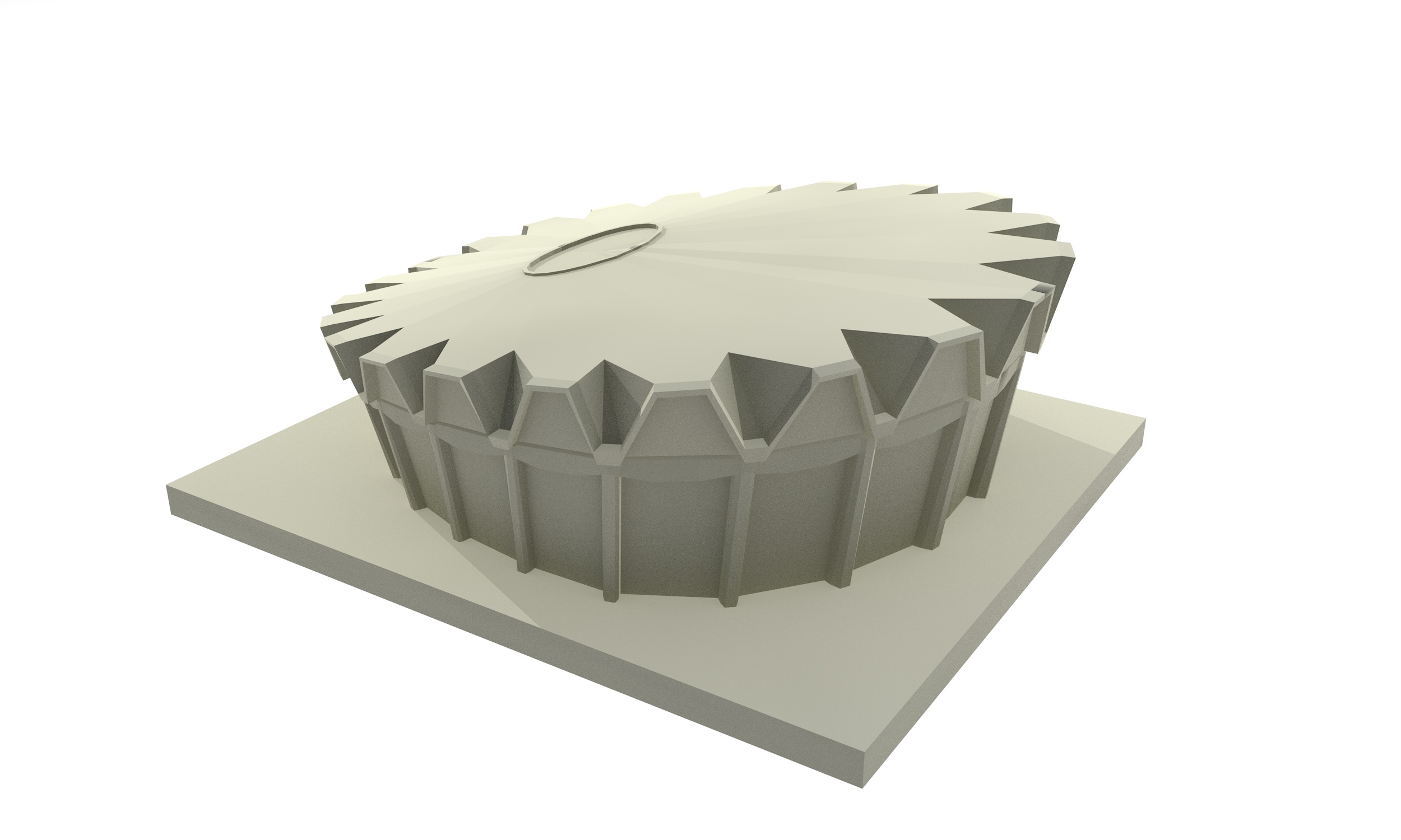
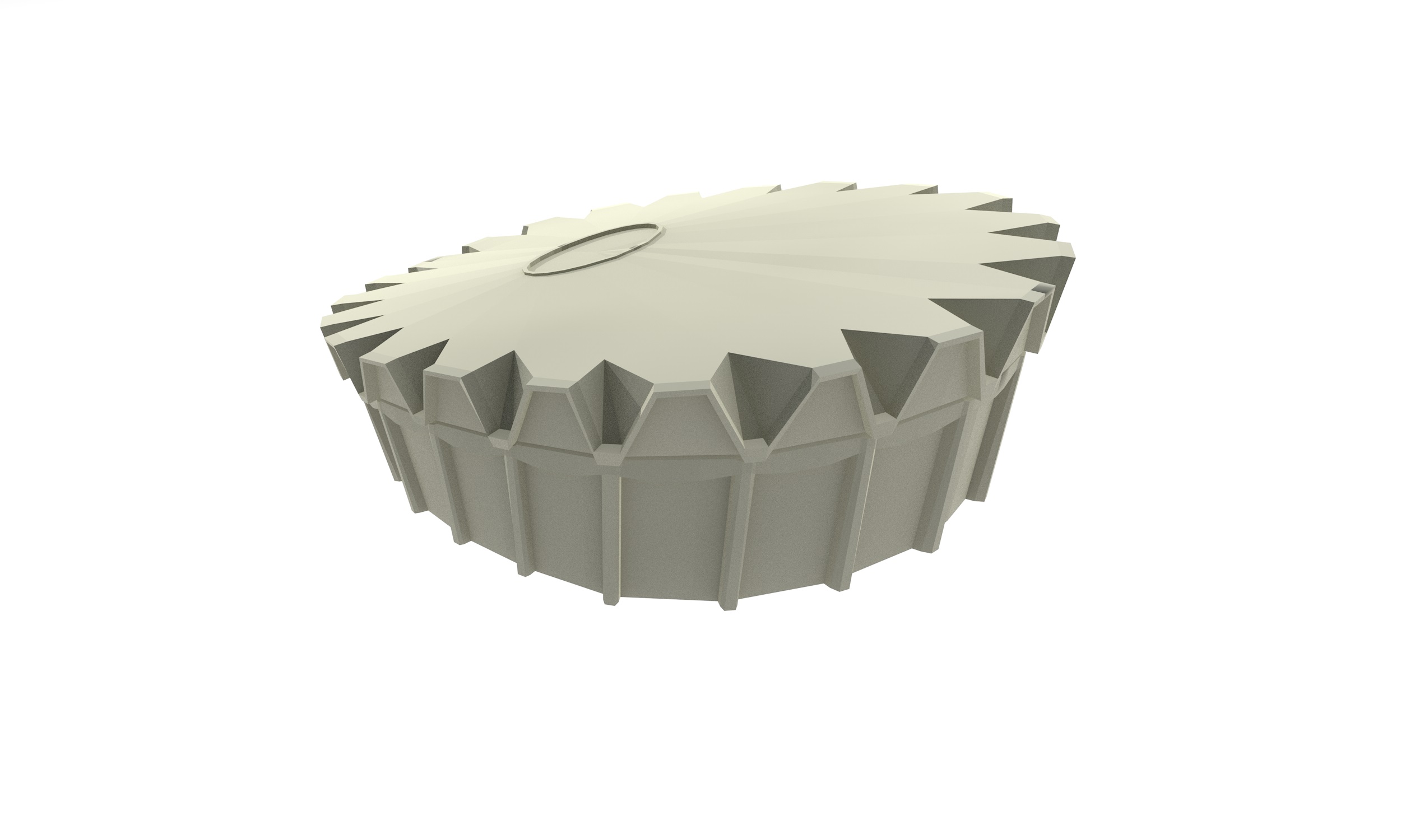
Conventional clamping system: The object to be machined is fixed with clamping jaws and clamping structures. The workpiece fixing structures are required for fragile geometry shapes of workpieces, for additive printed geometry models and freeform surfaces.
Option 2
Plunger impression system (form clamping system, Matrix GmbH developed): The plunger impression system can clamp complex workpieces with an accumulation of movable plungers in a form-fit manner. The clamping process of the workpiece is enabled by adapting the individual rams to the surface of the workpiece geometry and then fixing the rams in the new position.
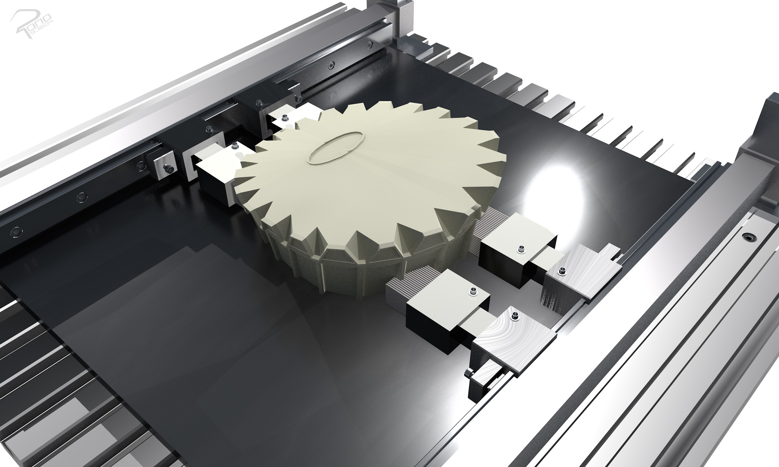
Advantages of this development
- Products with increased quality, reduced production time and more complex geometric shape can be manufactured in different ways.
- Furthermore, the two processes of the hybrid machine can be used independently of each other.
- Products can be manufactured in one production stage without subsequent assembly.
- Manufacturing with multimaterial properties is possible with this hybrid machine.
- Increased quality with reduced manufacturing time: The product is printed with the FLM process at normal or higher printing speeds (tending to be less accurate) and then machined with the milling tool.
References
- [1] Andreas Gebhardt. Additive Fertigungsverfahren: Additive Manufacturing und 3D-Drucken für Prototyping-Tooling-Produktion. Carl Hanser Verlag GmbH CoKG, 2017 (S. 117-131)
- [2] Carsten Feldmann and Anneliese Gorj. 3D-Druck und Lean Production: Schlanke Produktionssysteme mit additiver Fertigung. Springer-Verlag, 2017
- [3] Petra Fastermann. 3D-Druck/Rapid Prototyping: Eine Zukunftstechnologiekompakt erklärt. Springer-Verlag, 2012
- [4] Richard Hagl. 3d-druck-technologien. In Das 3D-Druck-Kompendium. Springer, 2015
- [5] Klaus-Dieter Arndt, Werner Bahmann, Lutz Barfels, Jürgen Bauer, Herbert Bernstein, Gert Böge, Ulrich Borutzki, Berthold Heinrich, Marcus Kampf, Arnfried Kemnitz, et al. Handbuch Maschinenbau: Grundlagen und Anwendungen der Maschinenbau-Technik. Springer-Verlag, 2014. (S. 25-26)
- [6] Eberhard Paucksch, Sven Holsten, Marco Linß, and Franz Tikal. Zerspantechnik. Vieweg + Teubner, 2008 (S. 1)
- [7] Eckart Uhlmann. „Führungen für schlitten und tische“, 2008. (S. 1ff)
- [8] Peter Hehenberger. Computerunterstützte Fertigung: Eine kompakte Einführung. Springer-Verlag, 2011. (S. 61)