On this page I would like to present you an part of my term paper, which I wrote at the Institute „Laser Application Technology (Lat)“ at the Ruhr-University Bochum (July 2018). The presented content and results were created by myself with the support and equipment of the Lat Institute.
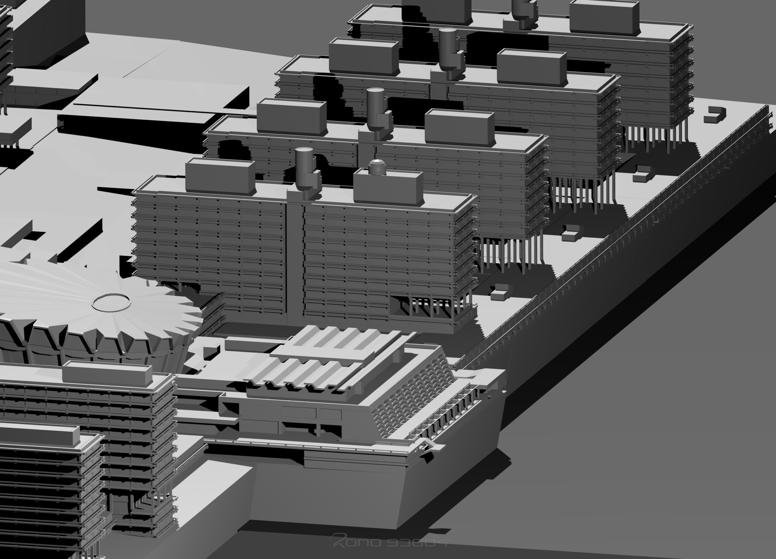
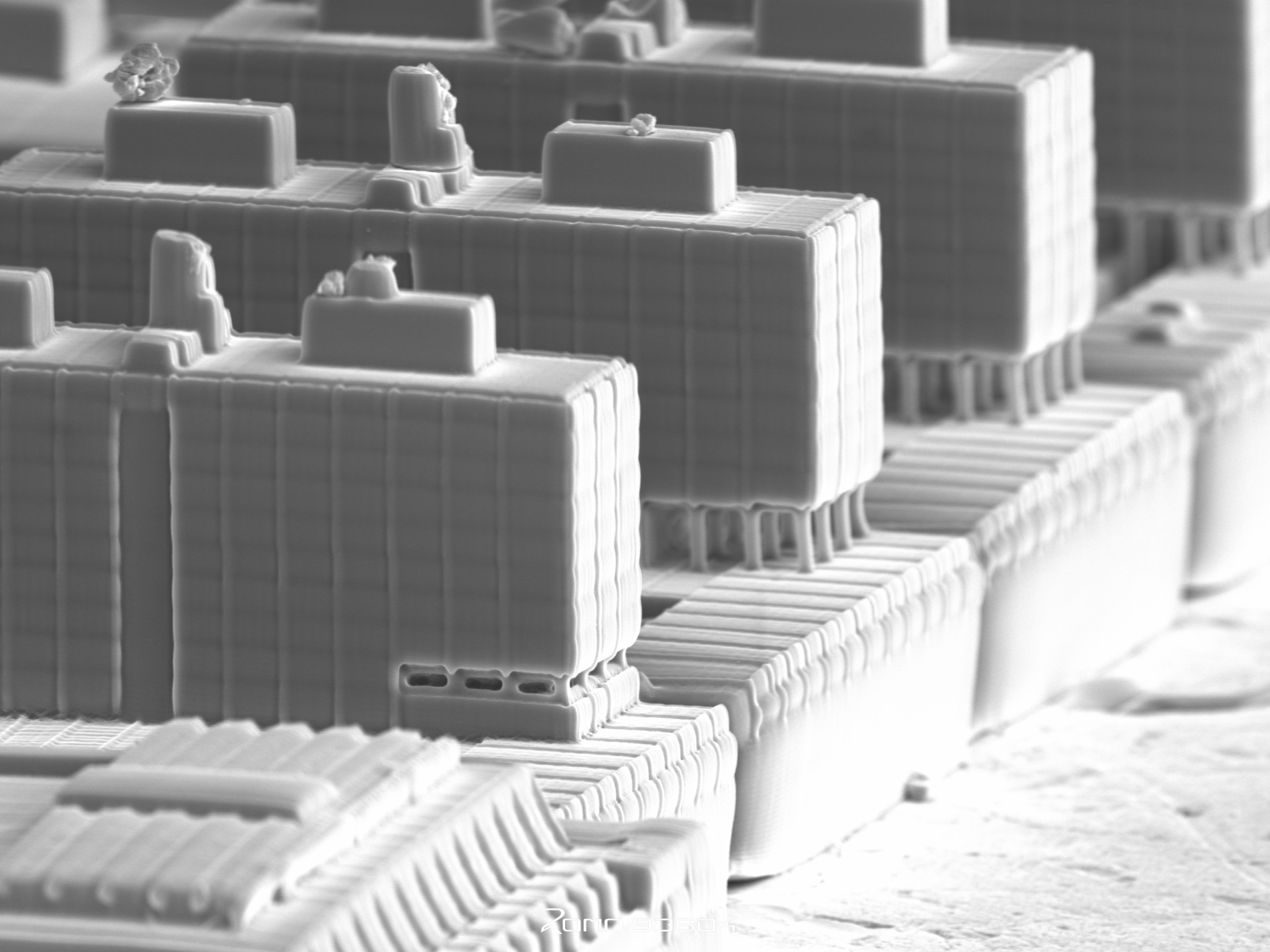
In the field of microtechnology, the production of complex microstructures is becoming increasingly important, which goes hand in hand with technological progress and the demand for ever smaller components. Many theoretical ideas of products and technologies could only be realized with the help of microtechnology, such as smartphones and computers . Within a smartphone, the optical processes of microtechnology are used by gyro sensors, displays, CPUs and other small components. So, the user of such devices comes in contact with microtechnology here, but hardly notices it due to the very small dimension. A new manufacturing technology is two-photon polymerization (2PP). It enables the creation of microstructures with a resolution in the nanometer range. Consequently, this technology can be used to create miniature models and components in the micrometer range.
A familiar object of comparison from everyday life helps to imagine the dimension of the printed component. In the semester project „Demonstration of the potential of a 3D laser printer in the field of microtechnology“, concepts were consequently developed to illustrate the scale of the miniaturized models in comparison to the real existing objects. For the implementation of this project, concise and well-known landmarks, means of transportation and architectures were first modeled in CAD software. Subsequently, a concept development for the manufacturing process took place. In the last step, those models were printed on ordinary everyday objects. The 2PP process offers many advantages in the creation of three-dimensional structures over other processes, such as single-photon polymerization (1PP). With 2PP, it is possible to create complex models without support structures because the process can create 3D structural geometries through controlled curing of a resin. The structures can be created on different materials with sufficiently low surface roughness. The structures are imaged using a scanning electron microscope (SEM).
Airplane motive on a screw
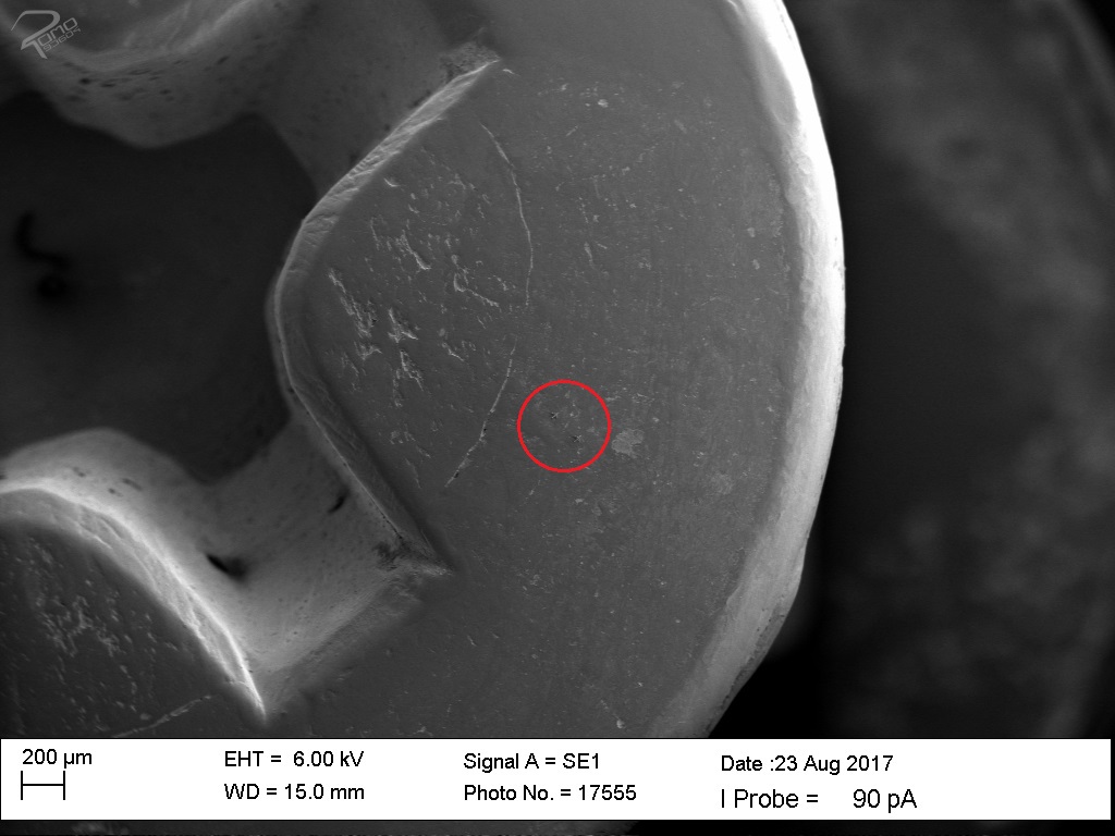
In this scene, the maximum print area of the scanner is increased with the separation of the model into several smaller elements. The scanner has a maximum lateral print area of approximately 55 µm. In addition to increasing the print area, the complexity increases due to the new elements that are created. As the model is The first motif is a model of an airplane, which is to be printed on a screw. A screw is a common object. The head of an M5 screw was chosen as the printing surface for this scene because of its smooth surface and suitable size. With a larger screw, the structures of the screw would not be recognizable in the images taken on the optical microscope and Scanning electron microscope (SEM). In the case of a smaller screw, the usable printable area would be too small, so that a more precise positioning of the laser would be necessary. The head surface of the screw has many small scratches and slight cracks. The screw is made of steel.
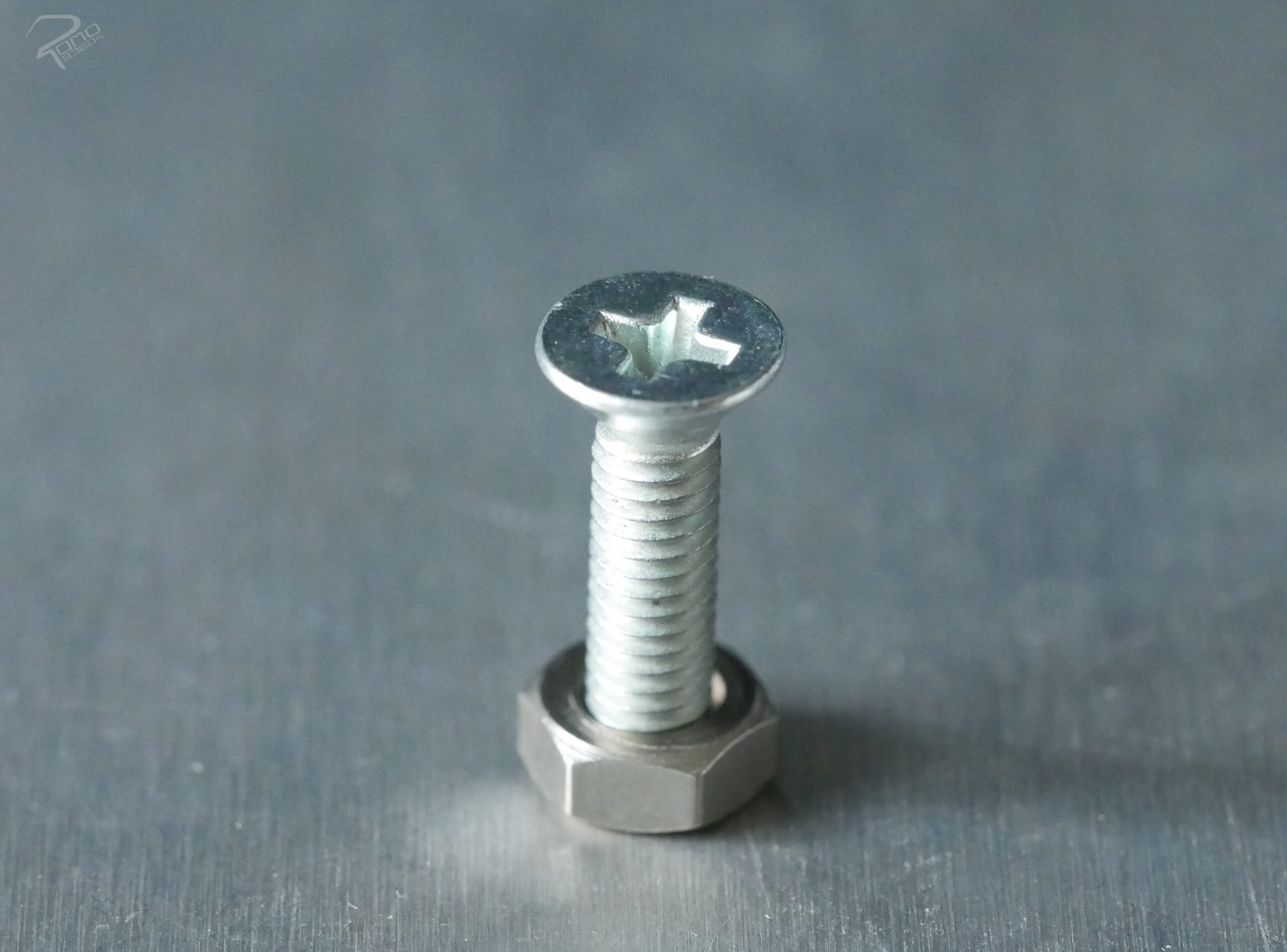
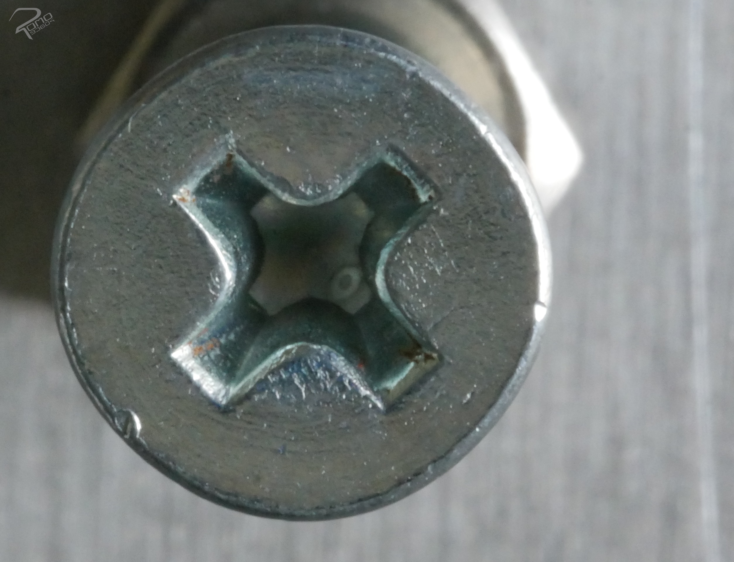
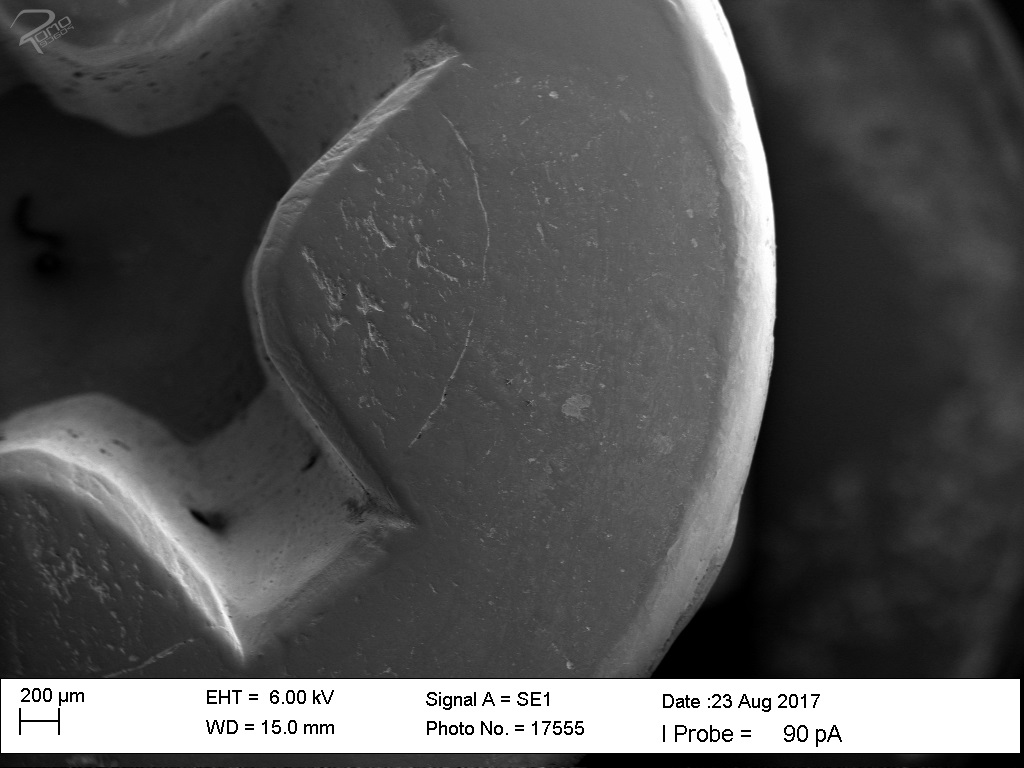
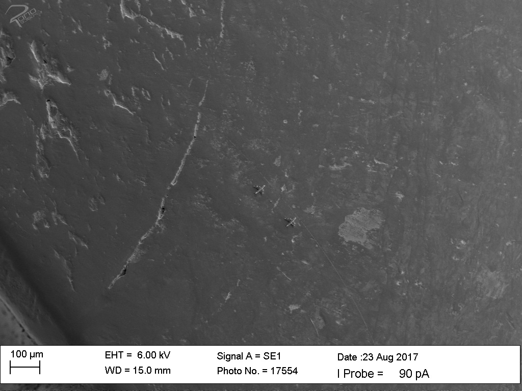
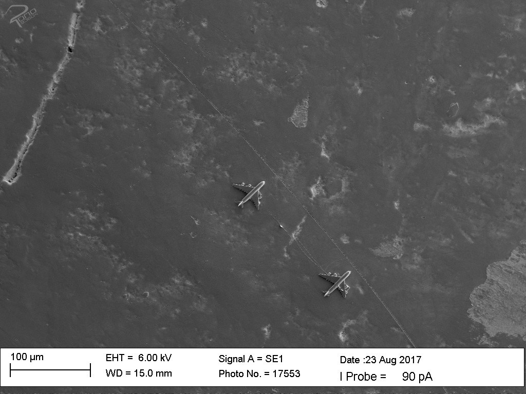
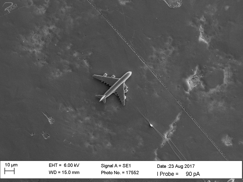
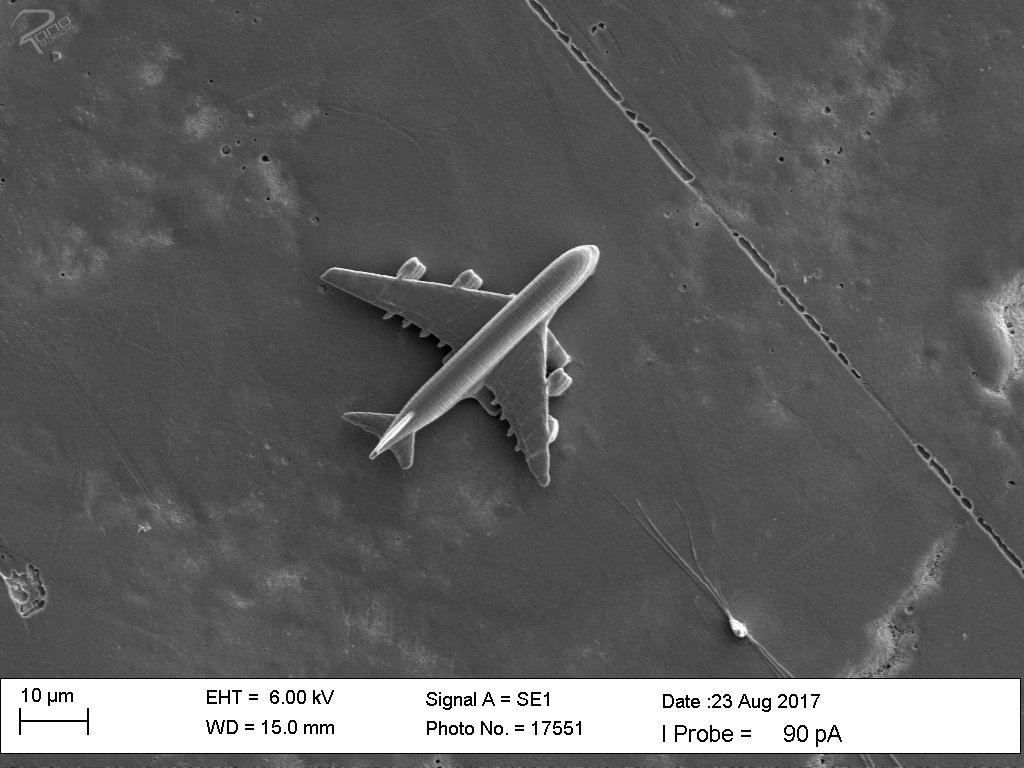
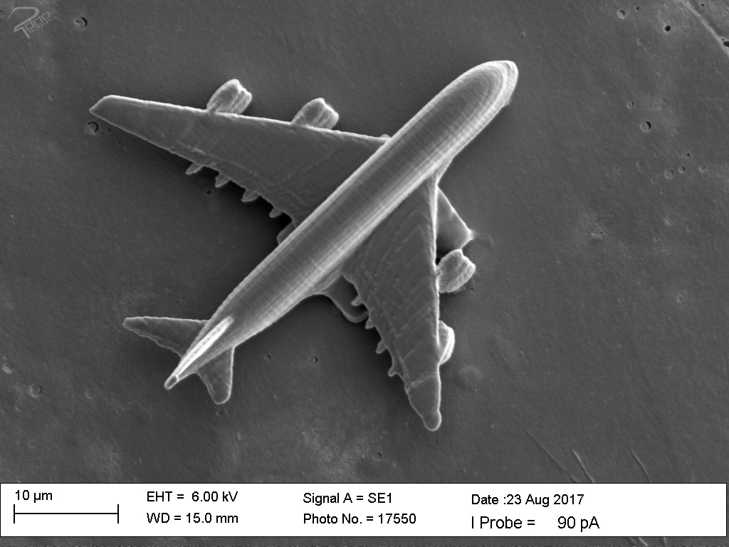
The experiment includes the objective to generate an airplane on a small area of a screw considering the stability of the airplane. When considering the objective, the following points must be clarified: Is the surface of the screw suitable for the pressure of the airplane on the given surface? Does the designed aircraft withstand the load of the wings as well as the load of the landing gear with the mass under the aspect that the object is filled? Is the contact of the landing gear sufficient for adhesion to the substrate? Is the quality of the pressure fair to the design?
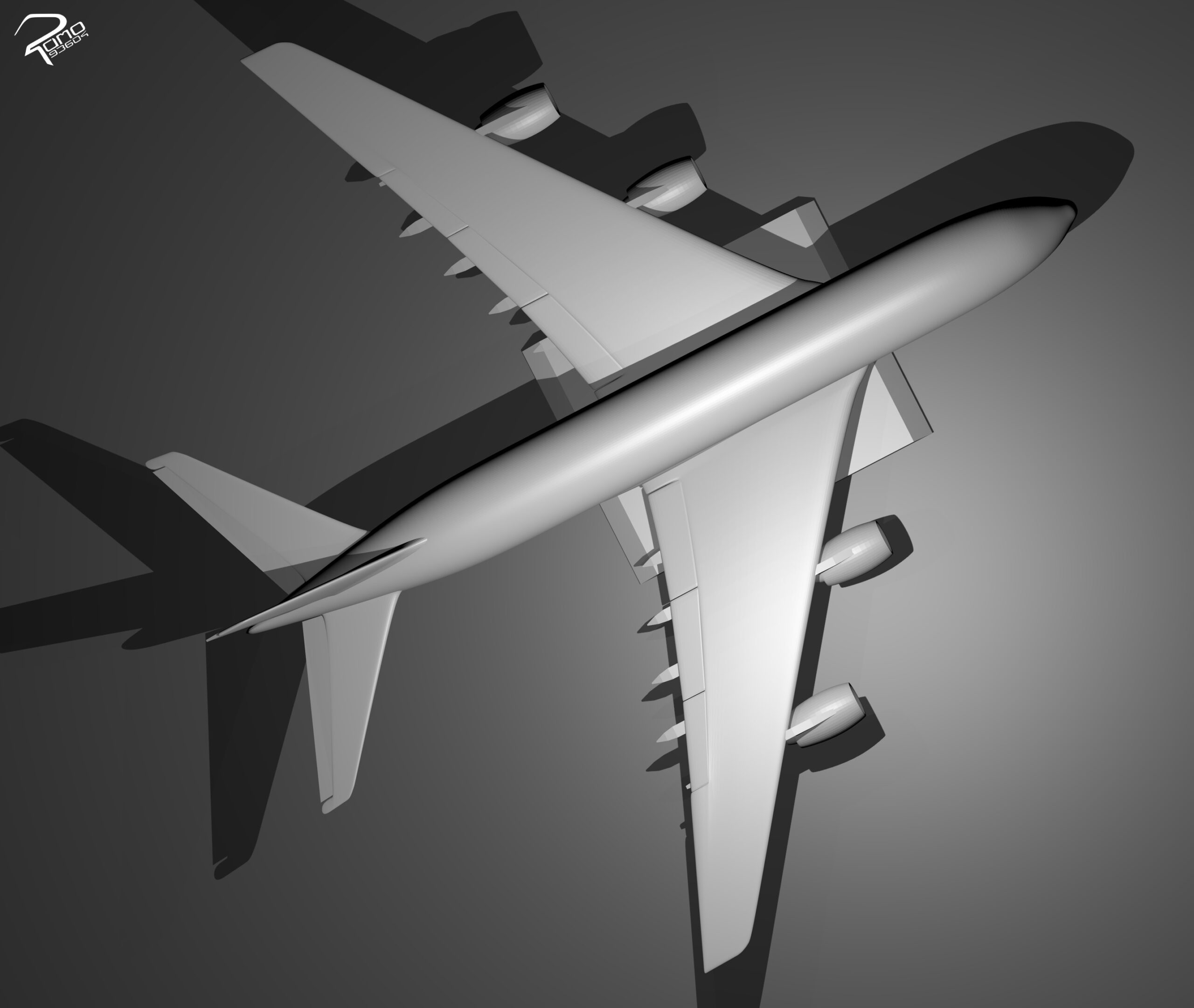
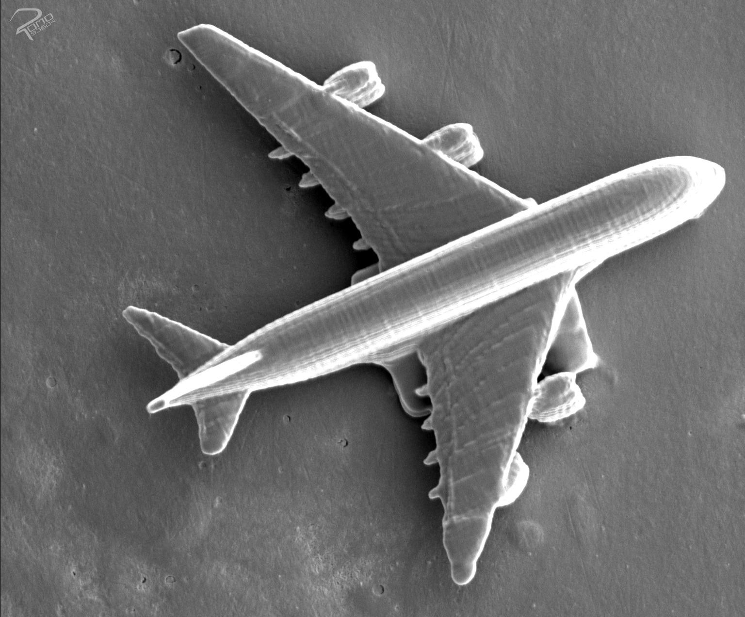
The fabrication of the aircraft structure on the screw leads to difficulties due to the surface characteristics of the screw. A screw is an everyday object, which does not have a high requirement for a smooth surface finish, because it is irrelevant to the purpose of the head of the screw. Therefore, screws have a lot of small damages, as well as cracks on the surface, which are very small and do not affect the stability of the screw. The created microstructures are very small, so the deep scratches and strong cracks, have an enormous impact on the positioning of the zero point in Z axis. The cracks can be seen only with the microscope. With the small size of the airplane, approx. 55 µm wide, 55 µm deep as well as 10-15 µm high, to the wrong height calibration lead. As a result, the aircraft either has no contact with the surface or the aircraft structure is printed below the surface.
Airplane winding tower structure on a 10 cent coin
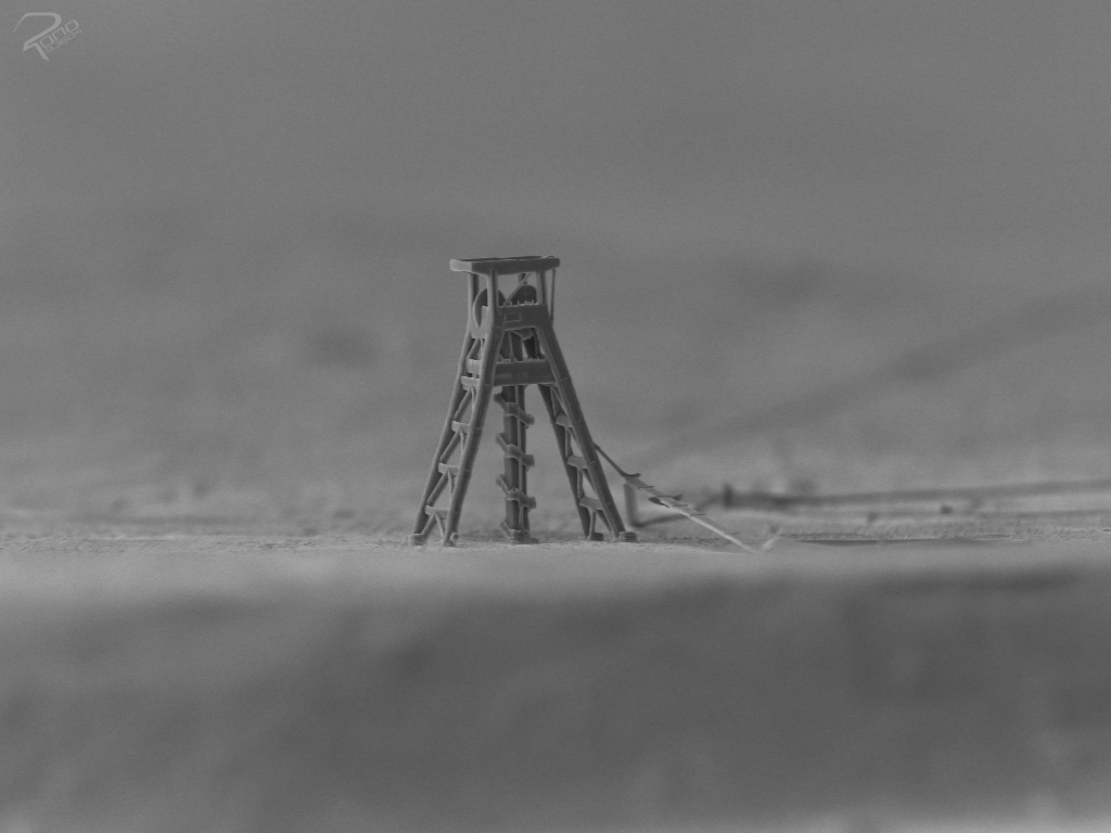
For the second theme, positioning the structure on a specific area of the substrate is an important part of the task. Since the structure to be printed is only a few microns and the enlargers also need to pick up the area of the substrate to get an idea of the size of the printed structure, only a small area is available for selection. To allow object recognition and an idea of how small the selected area is, the substrate selection must be a known object. Through this motif, the accuracy of the 2PP setup can be demonstrated. The selection is a winding tower printed on a 10 cent coin.


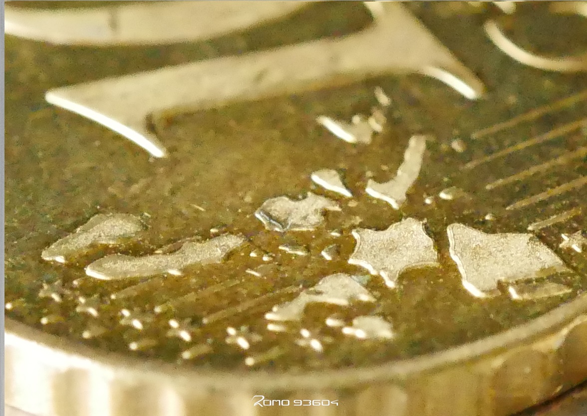
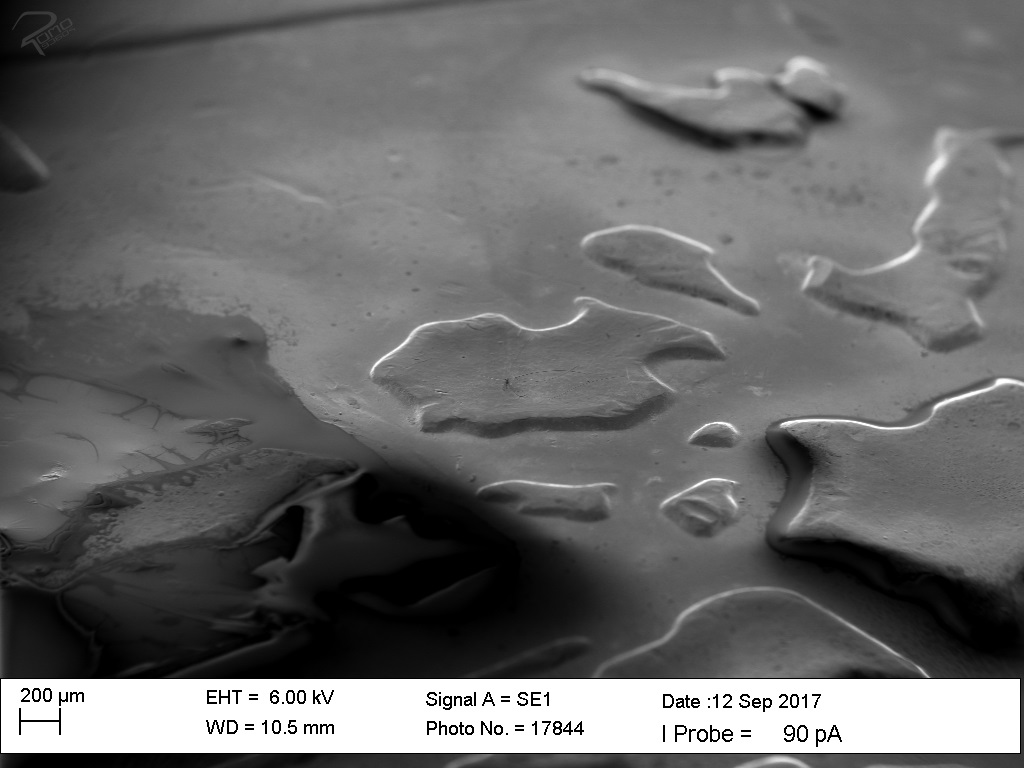
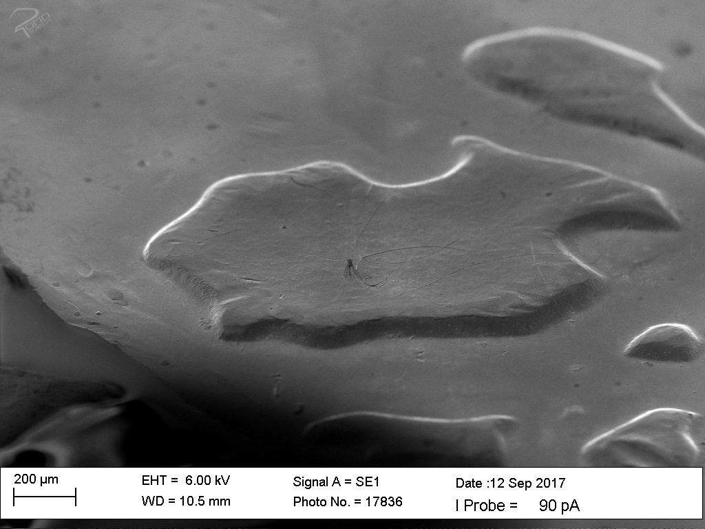
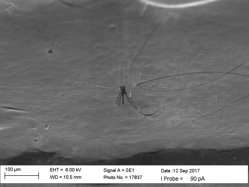
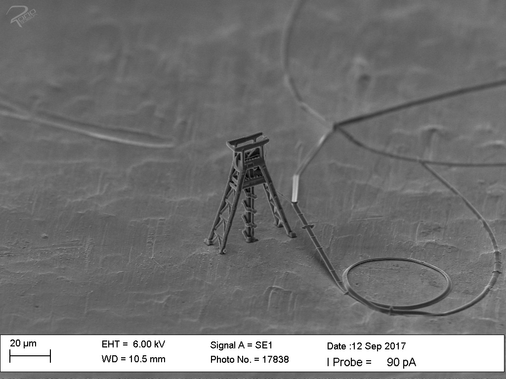
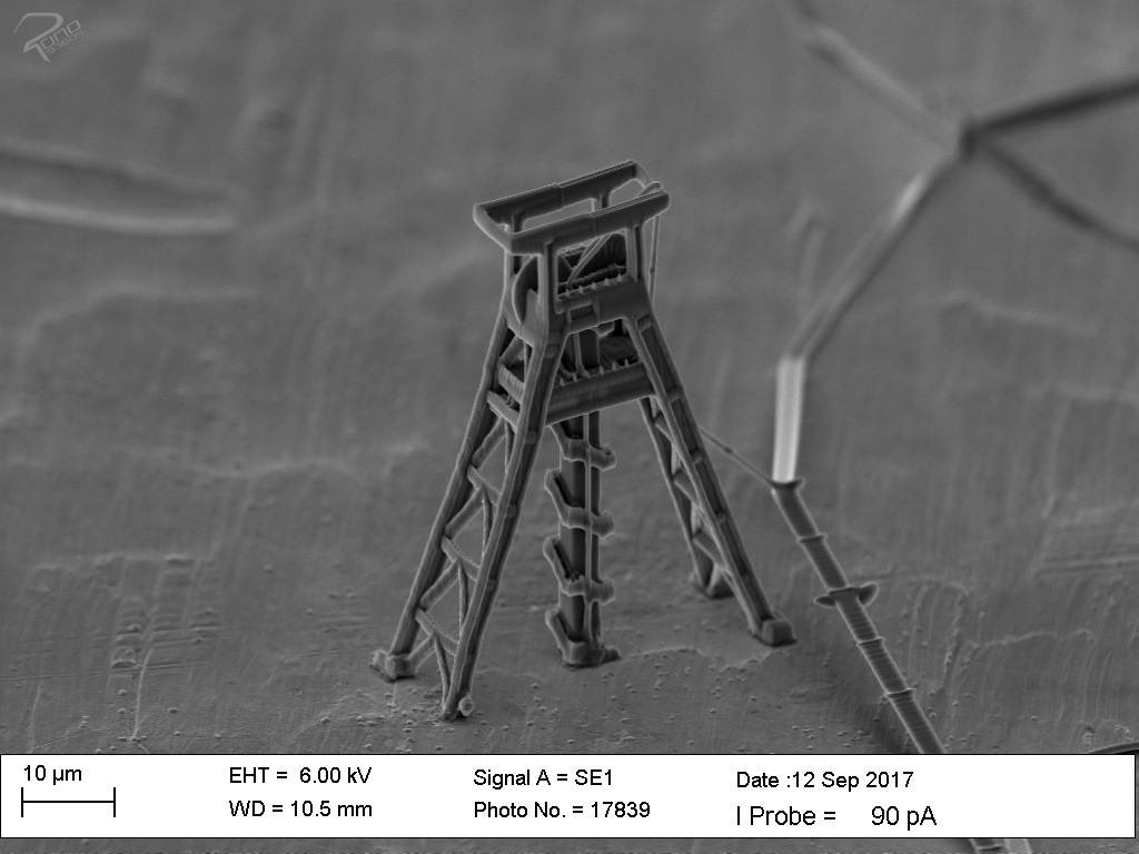
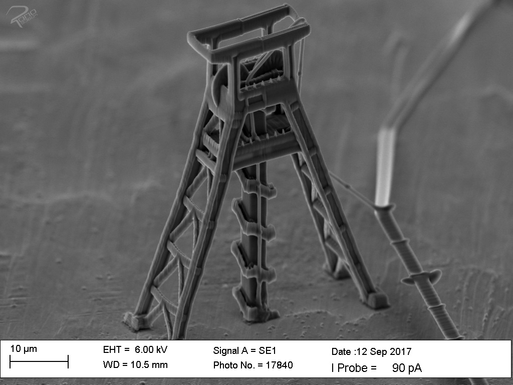
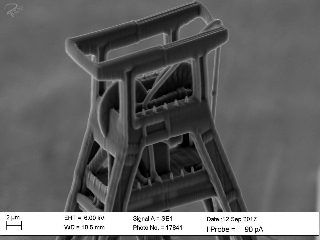
The motive „winding tower structure on a 10 cent coin“ contains the results and evaluation to position the constructed winding tower of Bochum on a certain position on the 10 cent coin. The 10 cent coin contains the minting of Europe with the respective countries, such as Germany, among others. Here the position of the approximate location of Bochum on the 10 cent coin is chosen. The following points are also part of the results and evaluation: Is the surface of the coin, specifically the area of Germany as well as the material of the coin suitable for printing the Bochum winding tower? Can the polymer construction of the winding tower withstand the loads of its own mass and the external forces? Is the contact of the small surfaces of the conveyor tower’s feet sufficient for adhesion to the substrate? Does the quality of the pressure correspond to the designed model?
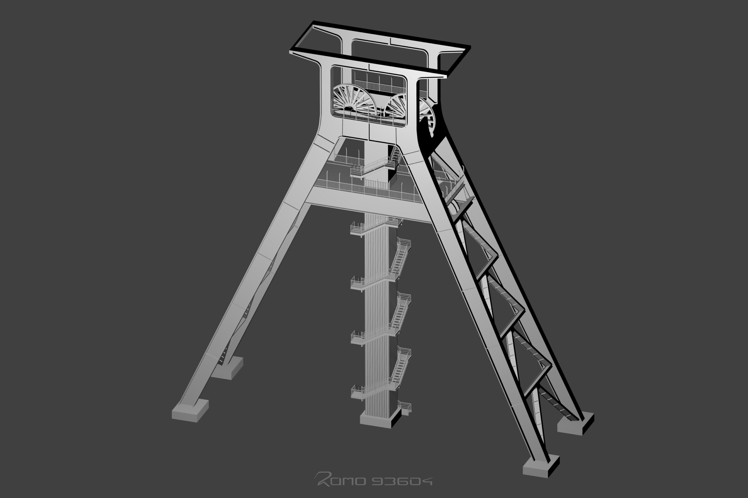
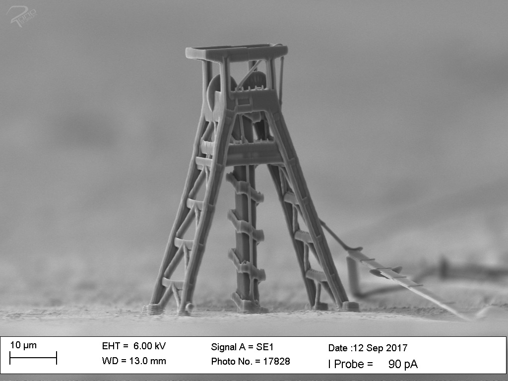
Some of the details are no longer visible or present when the structure is printed. Such as the fence grid is not present due to the size being too small, which is less than the minimum print width. The 2PP process is limited in resolution with the lasers used. The speed and power have an enormous influence on the quality. If the speed is increased and the power is kept constant, narrower lines are produced during printing. This makes the details more visible. Among other things the level of detail can be minimally increased by enlarging the edges. of the edges can be increased.
Ruhr University Bochum 3d model on a wristwatch hand
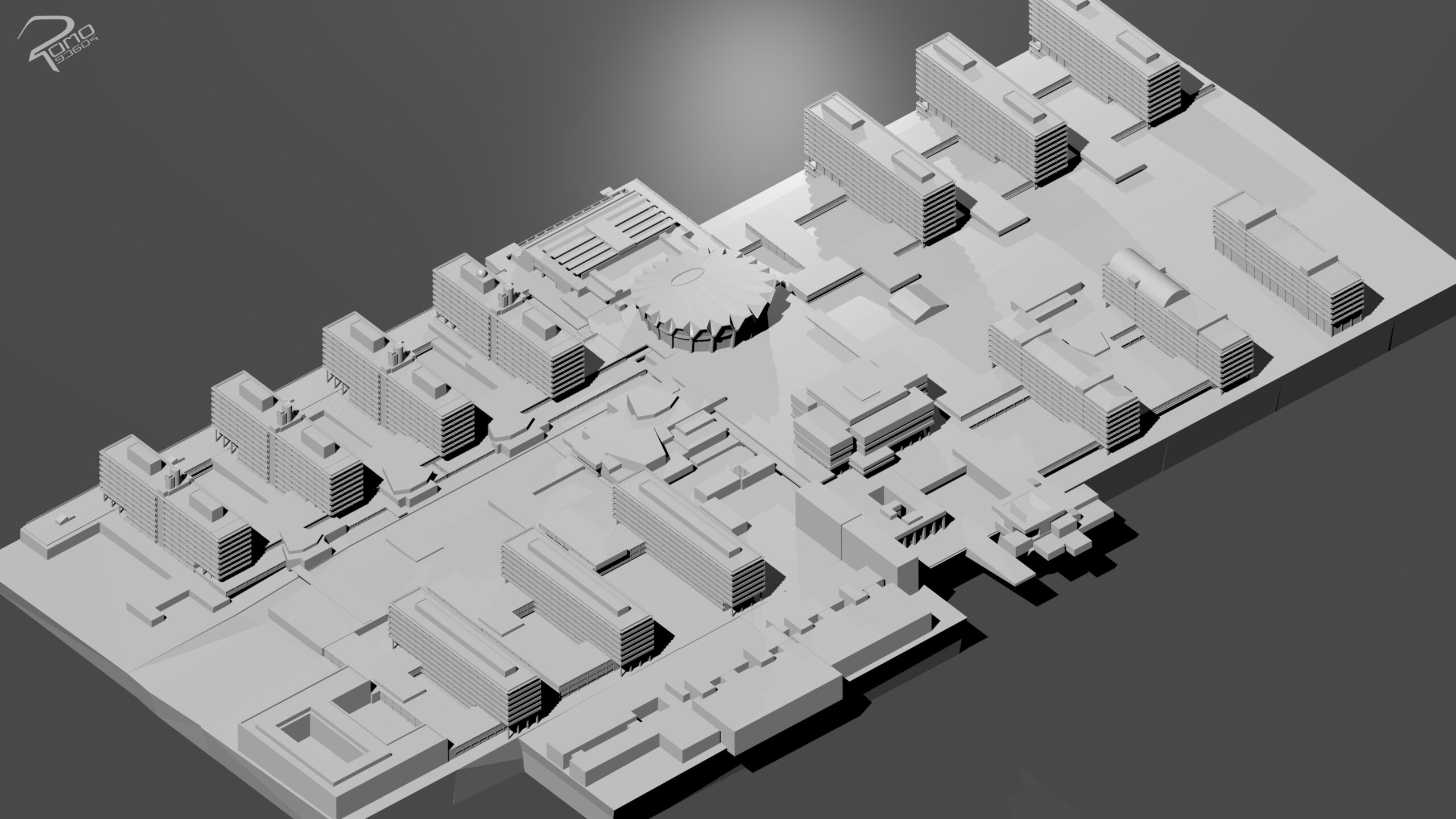
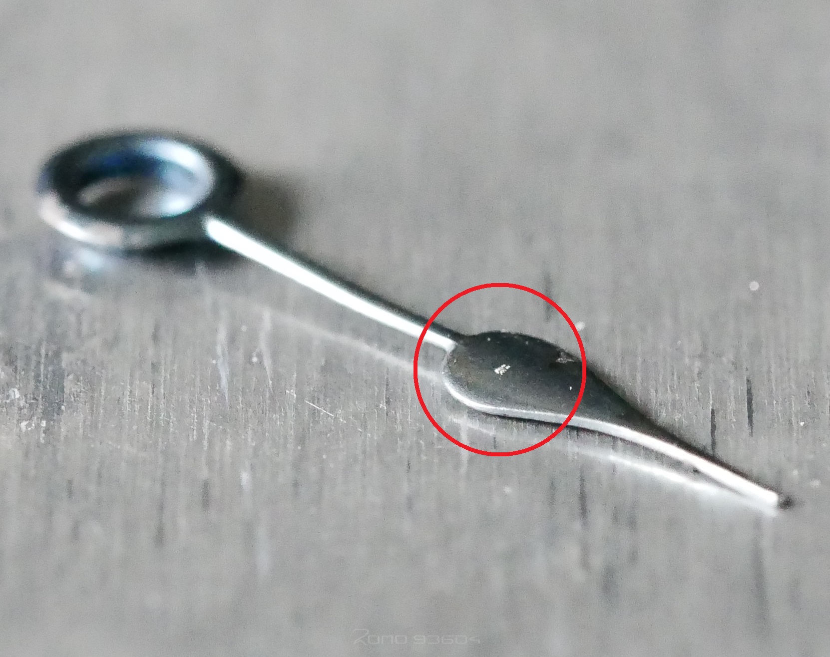
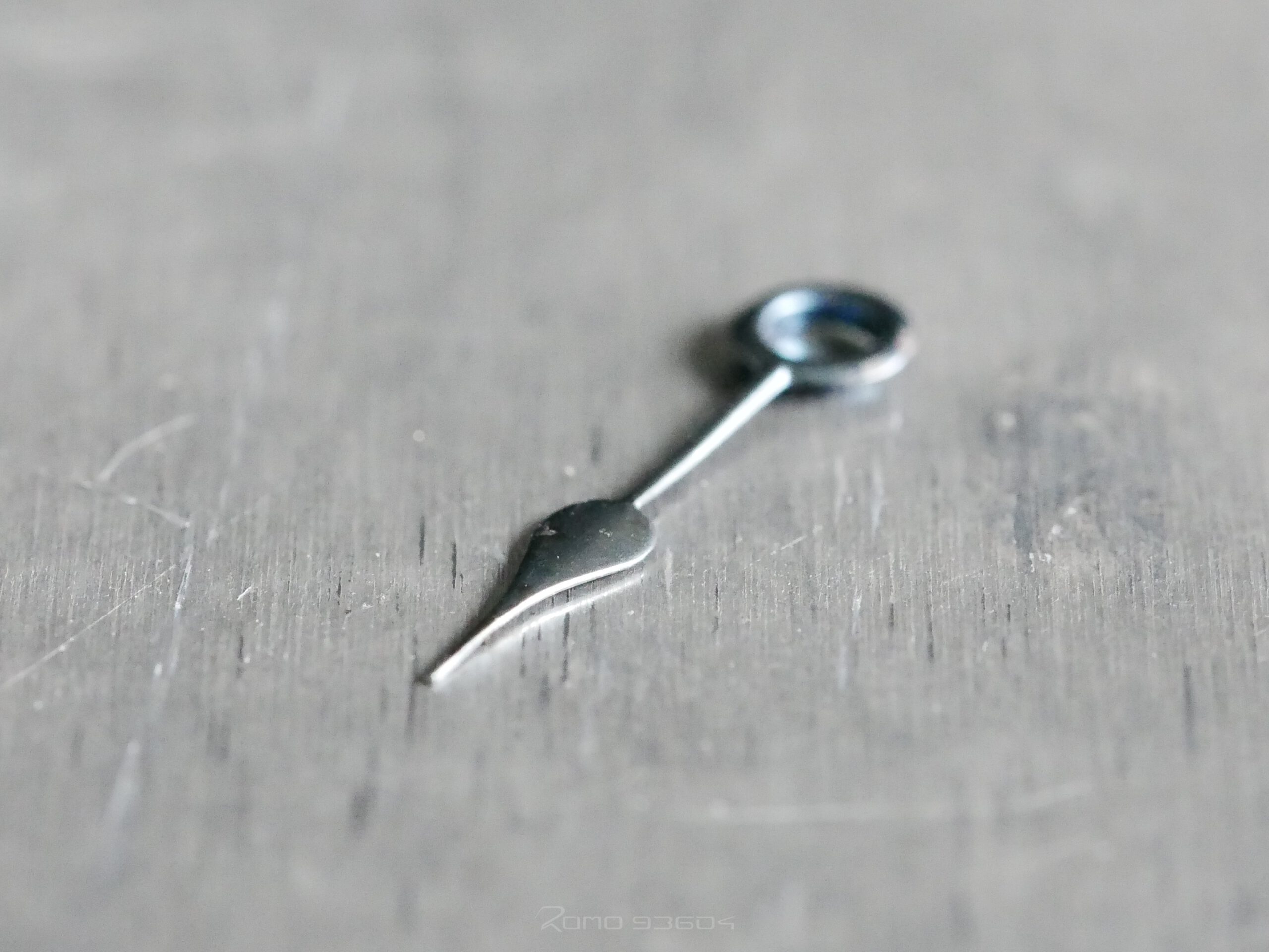
In this scene, the maximum print area of the scanner is increased with the separation of the model into several smaller elements. The scanner has a maximum lateral print area of approximately 55 µm. In addition to increasing the print area, the complexity increases due to the new elements that are created. As the model is enlarged over the print area of the scanner, the level of detail also rises. The model must be a certain size in order to print enough detail that serves to recognize the model. The elements must be printed with a high precision of less less than 1 micrometer in order to create a seamless connection. The Ruhr University in Bochum has a very complex building structure that is connected to different levels, due to its location. This is on a hill. The area of the Ruhr-University Bochum is about 4,5 km^2 and has a perimeter of a small city center. The wristwatch hand is made of metal. The dimensions of the wristwatch hand are 17 mm in length, 4 mm in width and 0.15 mm in thickness. The pressure area is the head of the watch hand, which has a radius of 1 mm and an area of 3 mm^2.
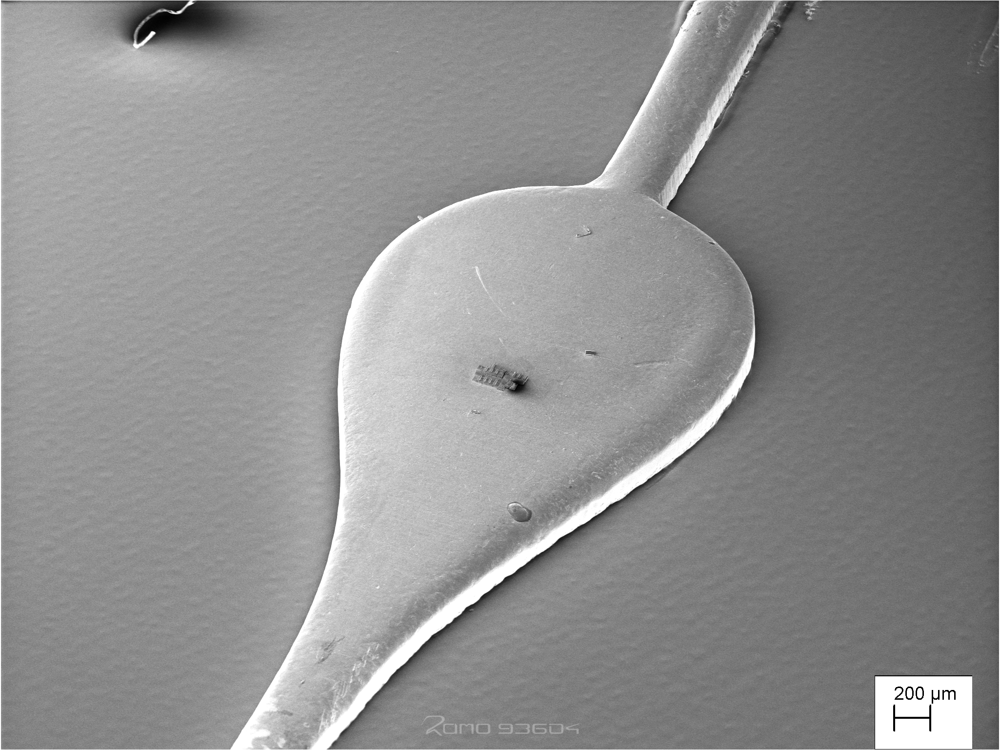
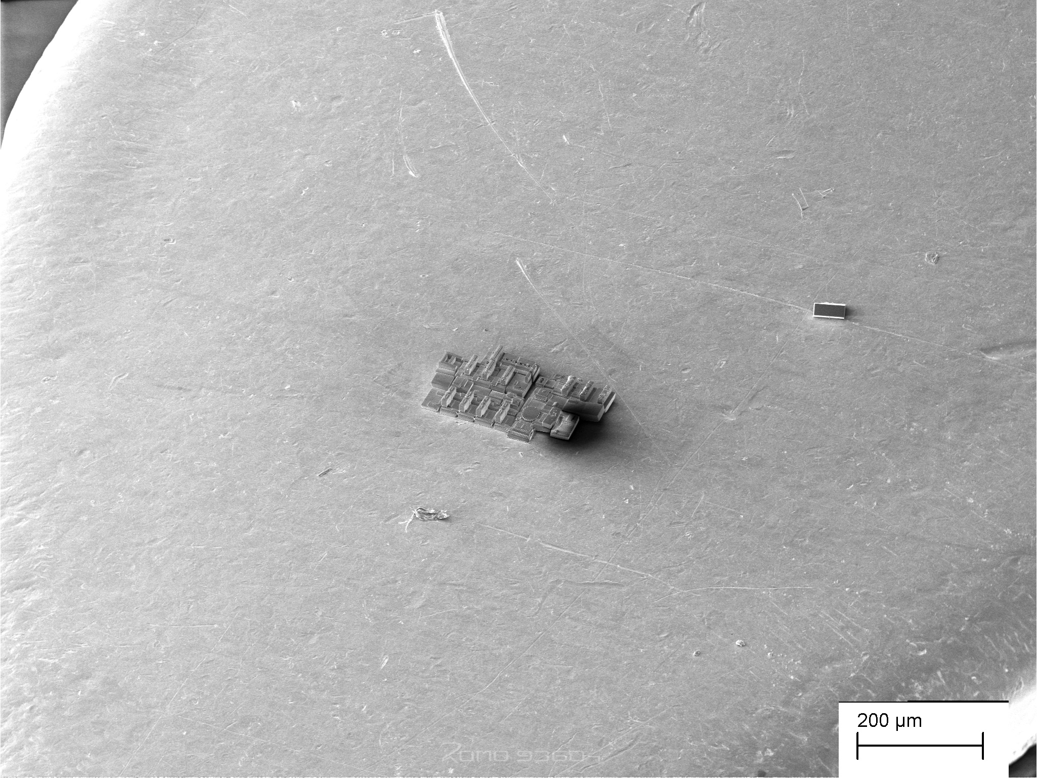
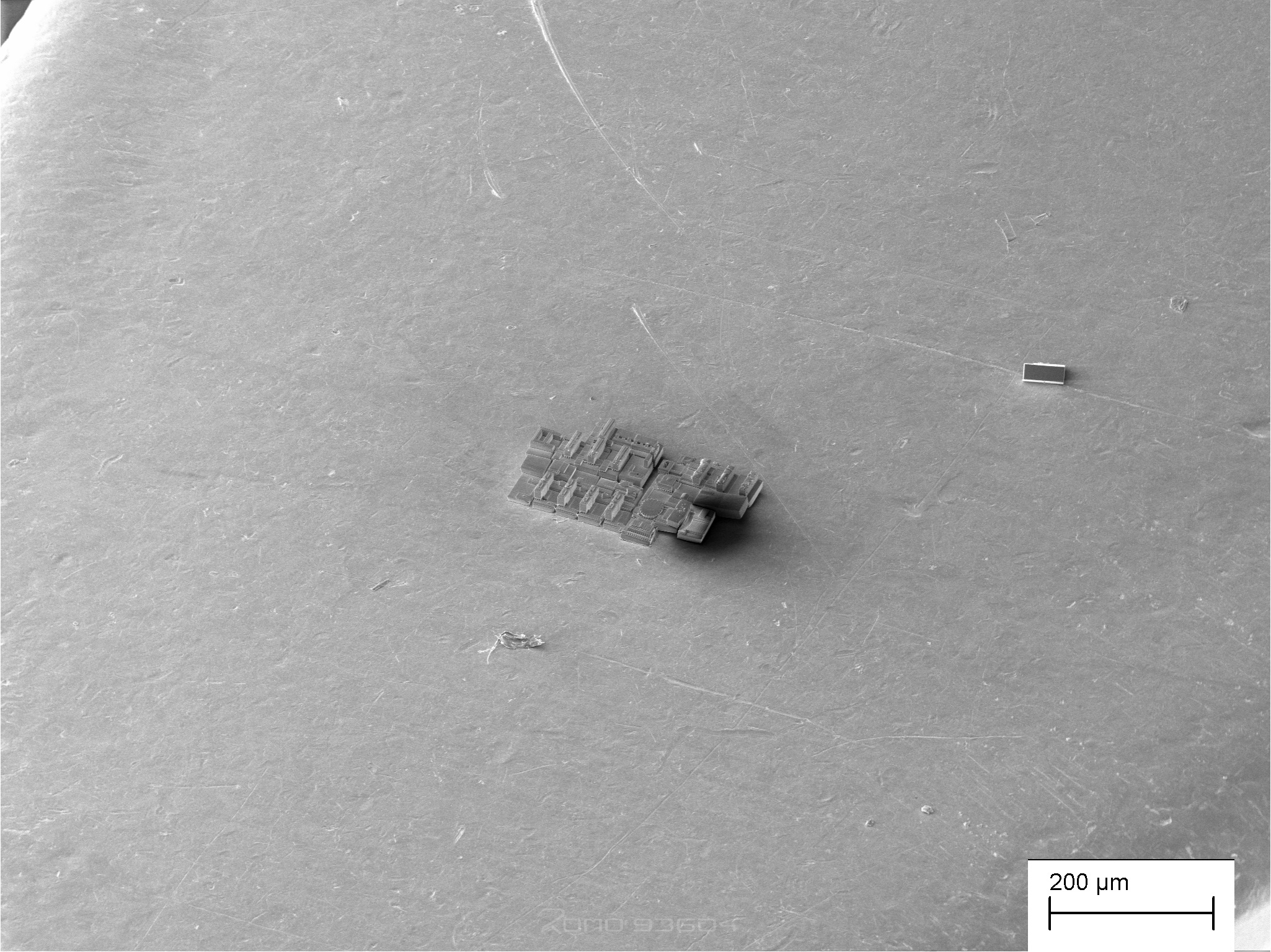
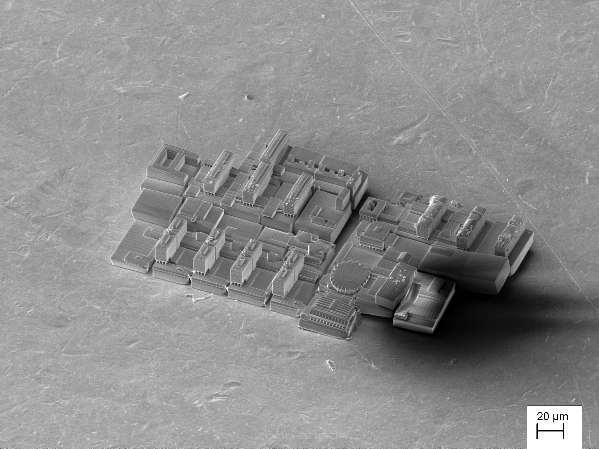
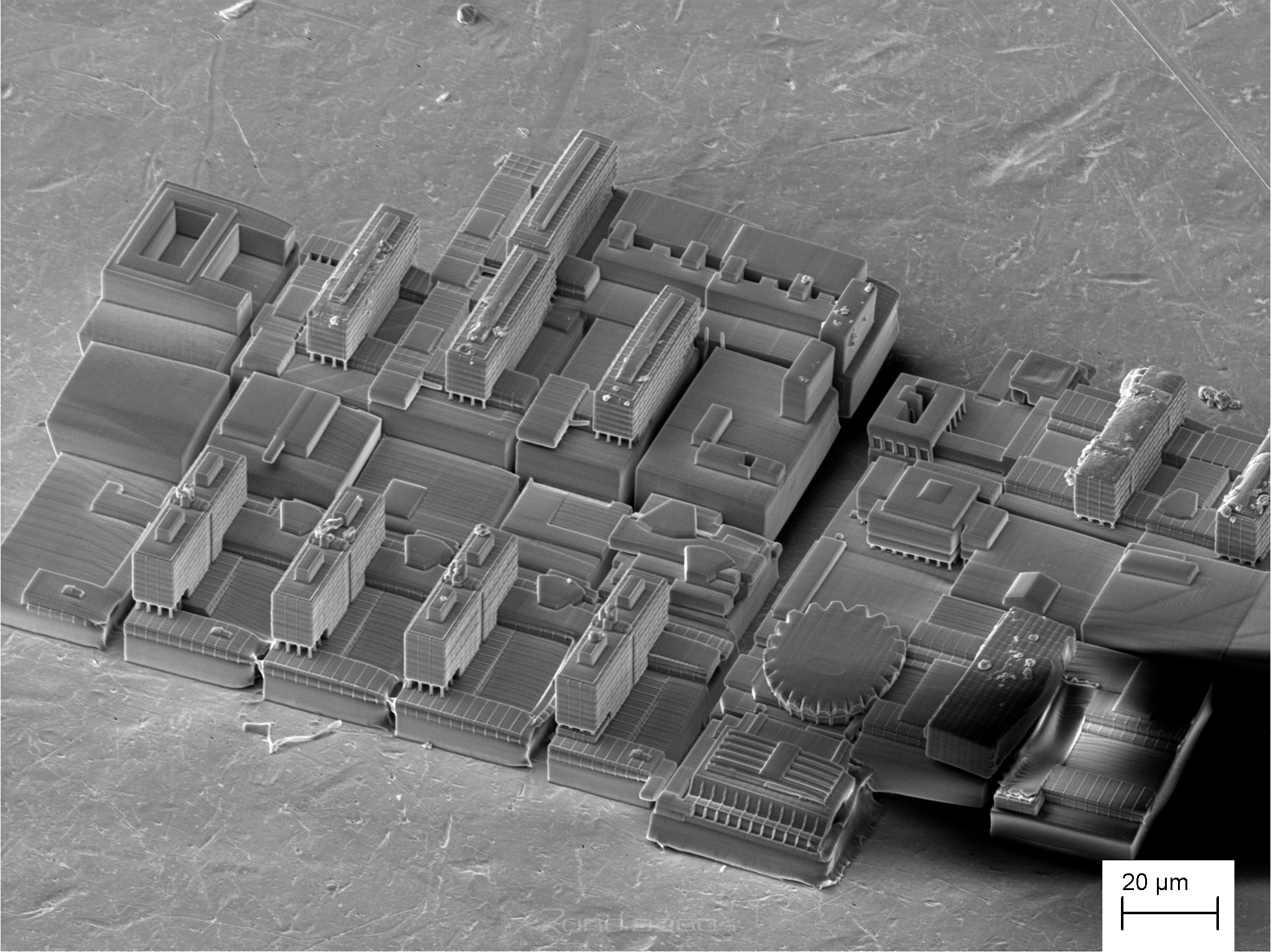
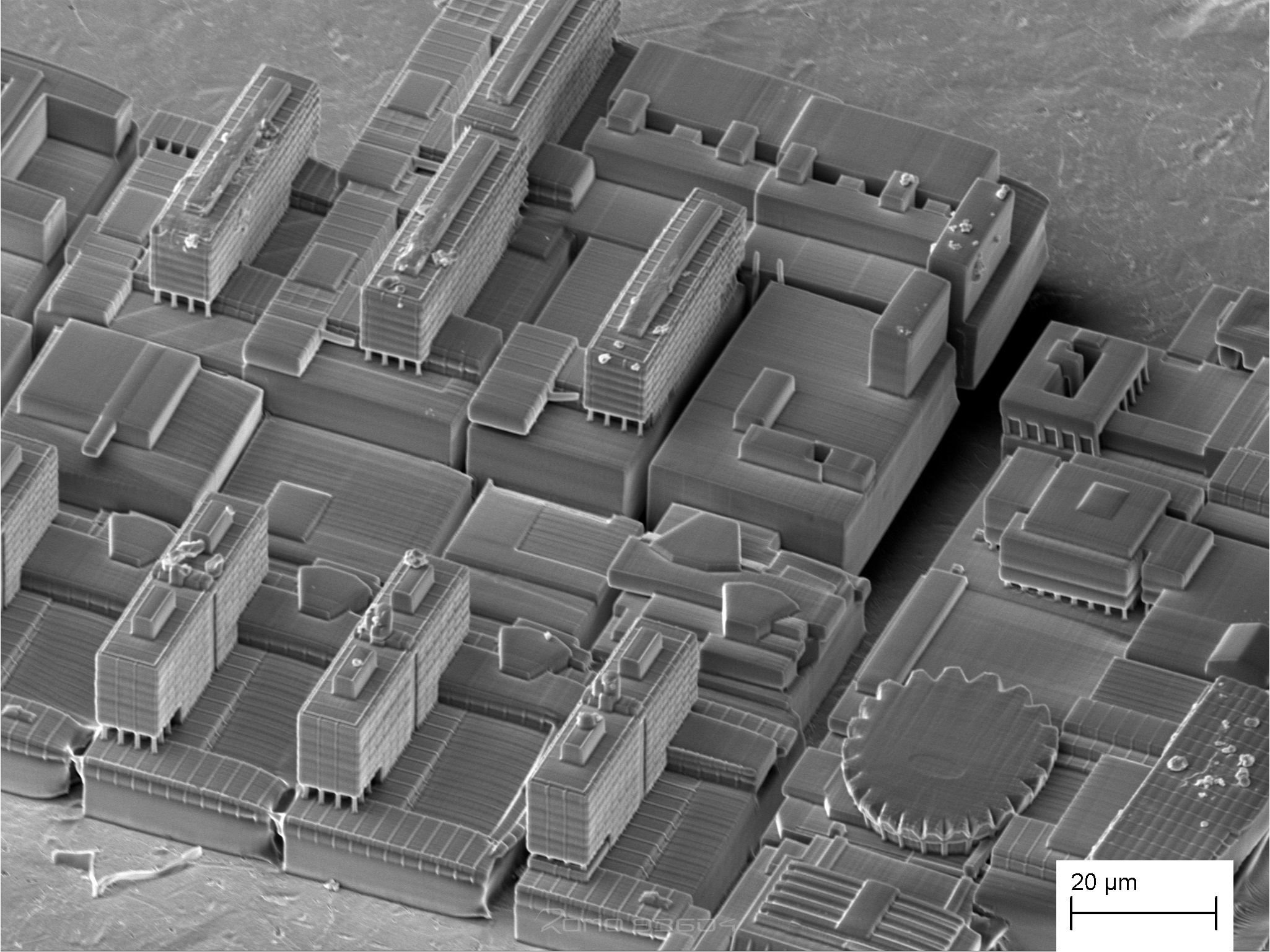
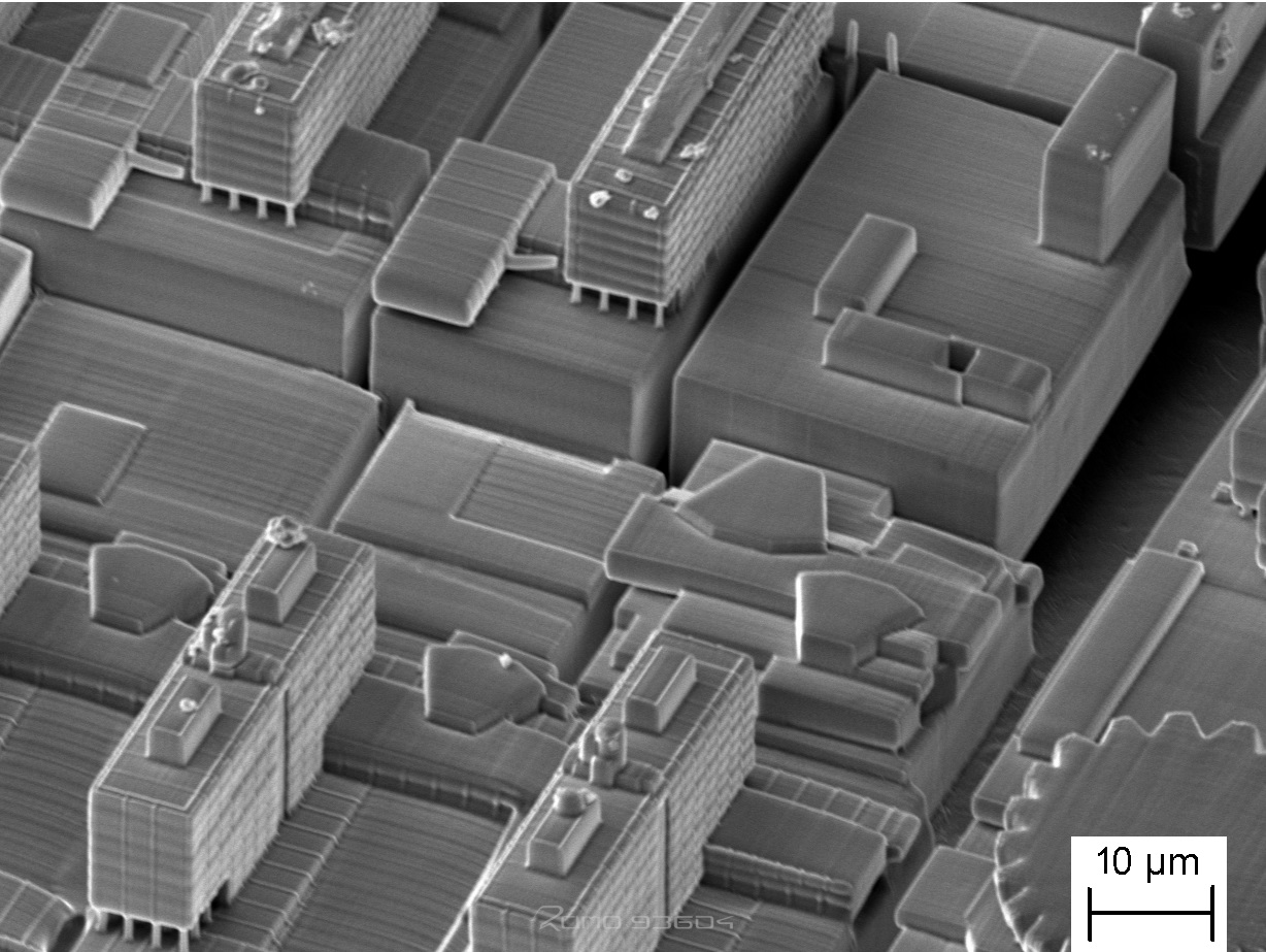
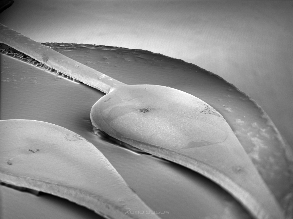
The evaluation to the motive, where the Ruhr-University Bochum is generated on a clock hand, involves the generation of multiple structures side by side at a larger scale. This task challenges the precision of the 2PP setup, which is designed to allow multiple structures to be printed with a spacing of less than 1 micron. The scanner only allows a precise writing area of about 3025 µm^2. The reason for the limitation is spherical aberration. This is 55 µm in width and 55 µm in length. The 3D model of the Ruhr-Universität Bochum has a fixed area of 108900 µm. This results in 36 structures. When the area is reduced, some elements of the printed structures become unrecognizable, due to the limited resolution of 0.1 µm in x and y direction. The comparison between the 3D model and the printed structure shows a small loss of detail.